Lighting system for vehicles

a technology for lighting systems and vehicles, applied in fixed installation, lighting and heating equipment, instruments, etc., can solve problems such as the unnecessary effect of waterproofing, and achieve the effects of convenient maintenance, small space, and convenient installation

Inactive Publication Date: 2005-08-11
MURAKAMI CORP
View PDF7 Cites 17 Cited by
  • Summary
  • Abstract
  • Description
  • Claims
  • Application Information

AI Technical Summary

Benefits of technology

[0008] In consideration of the above disadvantages, the present invention has been made. An object of the present invention is to provide a lighting system for vehicles which is able to be easily installed in an extremely small space, to be easily maintained, and to conserve its power consumption.

Problems solved by technology

Moreover, since the light source is not placed outside the vehicle, but placed within, an exchange and maintenance of the light source are made easier, and waterproofing becomes unnecessary.

Method used


Image

  • Lighting system for vehicles
  • Lighting system for vehicles
  • Lighting system for vehicles

Examples


first embodiment

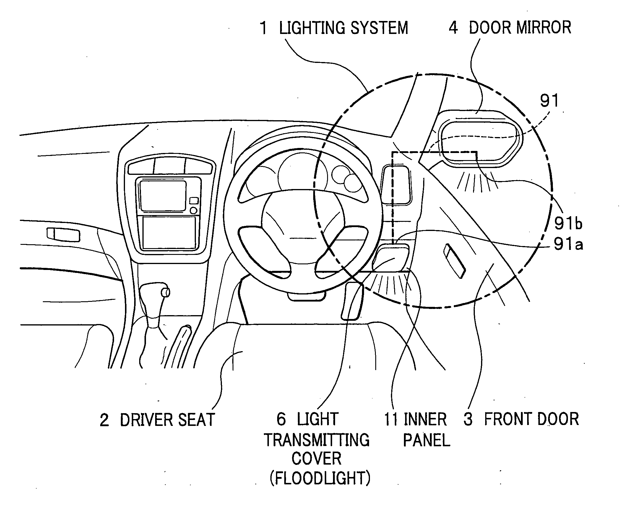
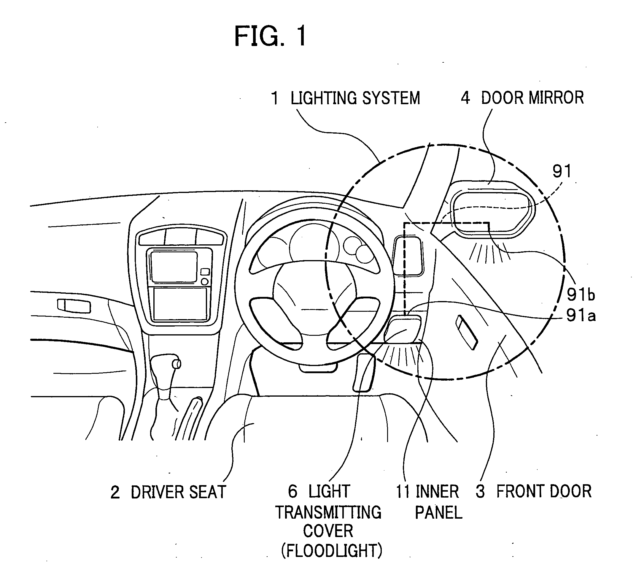
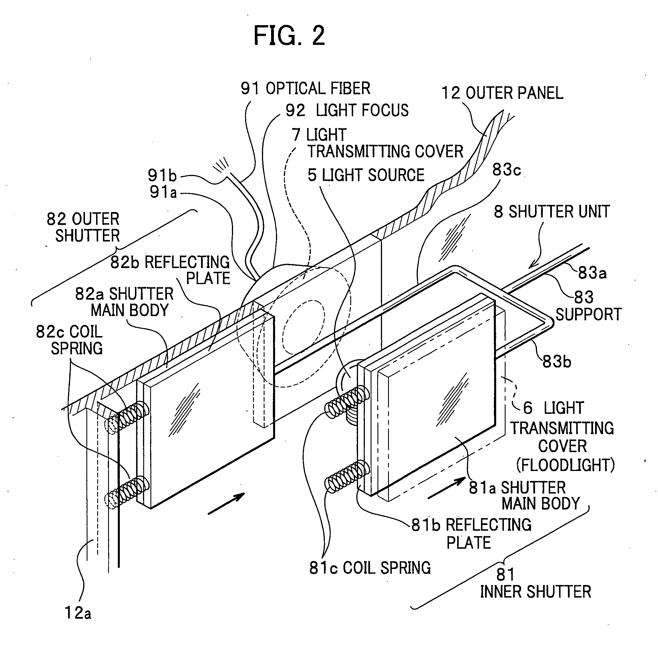
[0037]FIG. 1 is a perspective view depicting an interior of a vehicle where a lighting system according to the first embodiment is installed; and FIG. 2 is a perspective view depicting the lighting system itself. In FIG. 2, an inner panel 11 (see FIG. 1) is omitted for easy understanding.

[0038] A lighting system 1 according to the first embodiment serves as both in-vehicle and out-vehicle lighting systems. Specifically, the in-vehicle lighting system irradiates, from the inner panel 11 near a driver seat 2, an area around feet of a driver, and the out-vehicle lighting system irradiates, from an interior of a door mirror 4 on a front door 3, an area on a road below the door mirror 4.

[0039] Concretely, as shown in FIG. 2, the lighting system 1 includes a light source 5, such as one or more incandescent bulbs or LEDs, a light transmitting cover (floodlight) 6 placed on the driver's side relative to the light source 5 (thereinafter, referred to as “inner side”), a light transmitting c...

second embodiment

[0066] A lighting system according to the second embodiment of the present invention will be described below with reference to FIGS. 5A and 5B. FIGS. 5A and 5B are plan views depicting the lighting system according to the second embodiment. Specifically, FIG. 5A is a plan view of the lighting system when the front door 3 is closed; and FIG. 5B is a plan view of the lighting system when the front door 3 is opened. Note that, since the lighting system of the second embodiment differs from that of the first embodiment in that the arrangement of some components is modified, the same reference numerals are given to the same parts as those already described in the first embodiment, and duplicate description therefor is omitted.

[0067] A lighting system 1A according to the second embodiment serves as both out-vehicle and in-vehicle lighting systems. Specifically, the out-vehicle lighting system irradiates, from the interior of the door mirror 4, an area on a road below the door mirror 4 (F...


PUM


Abstract

Disclosed is a lighting system for vehicles which is able to be easily installed in an extremely small space, to be easily maintained, and to conserve its power consumption. The lighting system includes a light source placed inside a vehicle, and an optical fiber. This optical fiber has two ends, and light from the light source enters one end, whereas the light is sent out from the other end to irradiate any given area. Thanks to the optical fiber, the light source can be placed away from an area to be irradiated.

Description

BACKGROUND OF THE INVENTION [0001] 1. Field of the Invention [0002] A system consistent with the present invention relates to a lighting system used in a vehicle. [0003] 2. Description of the Related Art [0004] At present, some door mirrors attached on front doors of a vehicle are equipped with a lighting system which irradiates a lower area around the mirrors themselves. Thanks to this lighting system, when a driver and passengers get in and out of the vehicle, they can confirm conditions around their feet, for example, whether there are obstacles, boggy grounds, puddles or the like, even at night or in the dark, (refer to Japanese Unexamined Patent Application Publication No. 11-105621 (paragraph 0013, FIG. 1)). [0005] In addition, some door mirrors are equipped with an auxiliary turn signal unit. By use of this unit, a driver of a vehicle can surely indicate his or her intention to other vehicles or pedestrians even if they are positioned where they are hard to view primary turn ...

Claims


Application Information

Patent Timeline
Patent Type & Authority Applications(United States)
IPC IPC(8): B60Q1/00B60Q1/26B60Q1/32B60Q3/02B60R1/06B60R1/12F21S8/10F21V8/00
CPCB60Q1/0011B60Q1/2665B60R1/1207B60Q3/0216B60Q1/323B60Q3/217B60Q1/324
Inventor MATSUURA, MASAAKI
Owner MURAKAMI CORP
Why Eureka
Try Eureka