Optical connection closure having at least one connector port

a technology of optical fiber connection and connector port, which is applied in the field of enclosures, can solve the problems of difficult entry into the closure, difficult configuring of the closure, and difficulty in reconfiguring the optical fiber connection in the aerial splice closure,

Active Publication Date: 2005-08-11
CORNING OPTICAL COMM LLC
View PDF13 Cites 236 Cited by
  • Summary
  • Abstract
  • Description
  • Claims
  • Application Information

AI Technical Summary

Benefits of technology

[0007] To achieve the foregoing and other objects, and in accordance with the purpose of the present invention as embodied and broadly described herein, the present invention provides various embodiments of an optical connection closure having one or more connector ports located in an external wall of the closure for receiving connectorized optical fibers on the inside of the closure and pre-connectorized fiber optic drop cables on the outside of the closure. An optical connection closure according to the present invention permits a less experienced and less skilled filed technician to establish desired optical connections in a fiber optic communications network and to reconfigure optical connections after initial installation of the closure at a branch point along the length of a feeder, distribution or branch cable of the network. An optical connection closure according to the present invention also permits optical connections to be established and reconfigured without the need for entering the closure and performing splices or adapter sleeve connections after the initial installation.
[0010] In yet another exemplary embodiment, the present invention provides a fiber optic communications network including a distribution cable comprising a plurality of optical fibers, a mid-span access location provided along the length of the distribution cable, an optical connection closure positioned in the fiber optic network around the mid-span access location, the closure comprising one or more connector ports for receiving a connectorized optical fiber of the distribution cable on the inside of the closure and a pre-connectorized drop cable on the outside of the closure, at least one distribution cable opening for receiving the distribution cable extending through the closure, and opposed end walls positioned around the distribution cable and affixed to a base to retain the distribution cable between the opposed end walls of the closure.

Problems solved by technology

In particular, it is often difficult to enter the closure and to identify an optical fiber of the distribution cable to be interconnected with an optical fiber of a particular drop cable.
In either case, the process of entering and configuring the closure is not only time consuming, but frequently must be accomplished by a highly skilled field technician at significant cost and under field working conditions that are less than ideal.
Reconfiguring optical fiber connections in an aerial splice closure is especially difficult, particularly in instances where at least some of the optical fibers of the distribution cable extend uninterrupted through the closure, since the closure cannot be readily removed from the distribution cable.
Further, once the optical connections are made, it is often labor intensive, and therefore costly, to reconfigure the existing optical connections or to add additional optical connections.

Method used


Image

  • Optical connection closure having at least one connector port
  • Optical connection closure having at least one connector port
  • Optical connection closure having at least one connector port

Examples


Embodiment Construction

[0023] The present invention will now be described more fully hereinafter with reference to the accompanying drawings in which exemplary embodiments of the invention are shown. This invention may, however, be embodied in many different forms and should not be construed as limited to the embodiments set forth herein. These exemplary embodiments are shown and described so that this disclosure will be both thorough and complete, and will fully convey the scope of the invention to those skilled in the art. Like reference numbers refer to like elements throughout the various drawings.

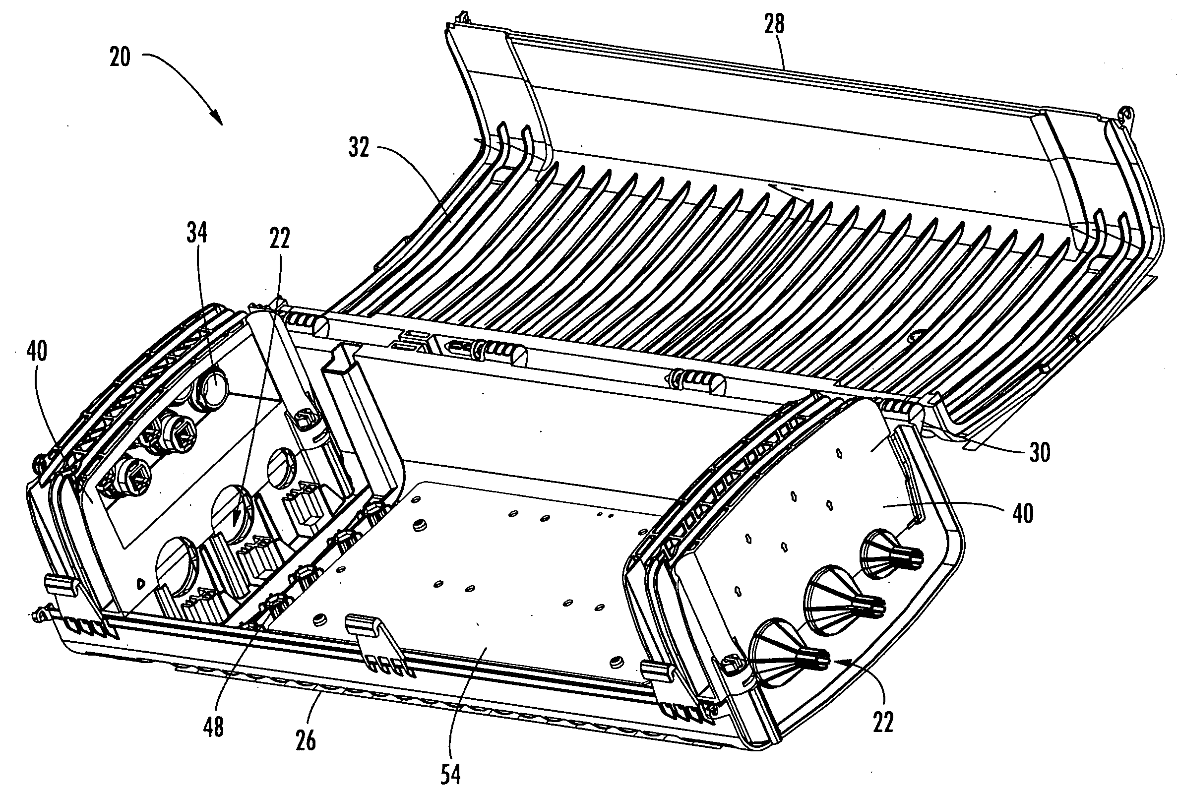
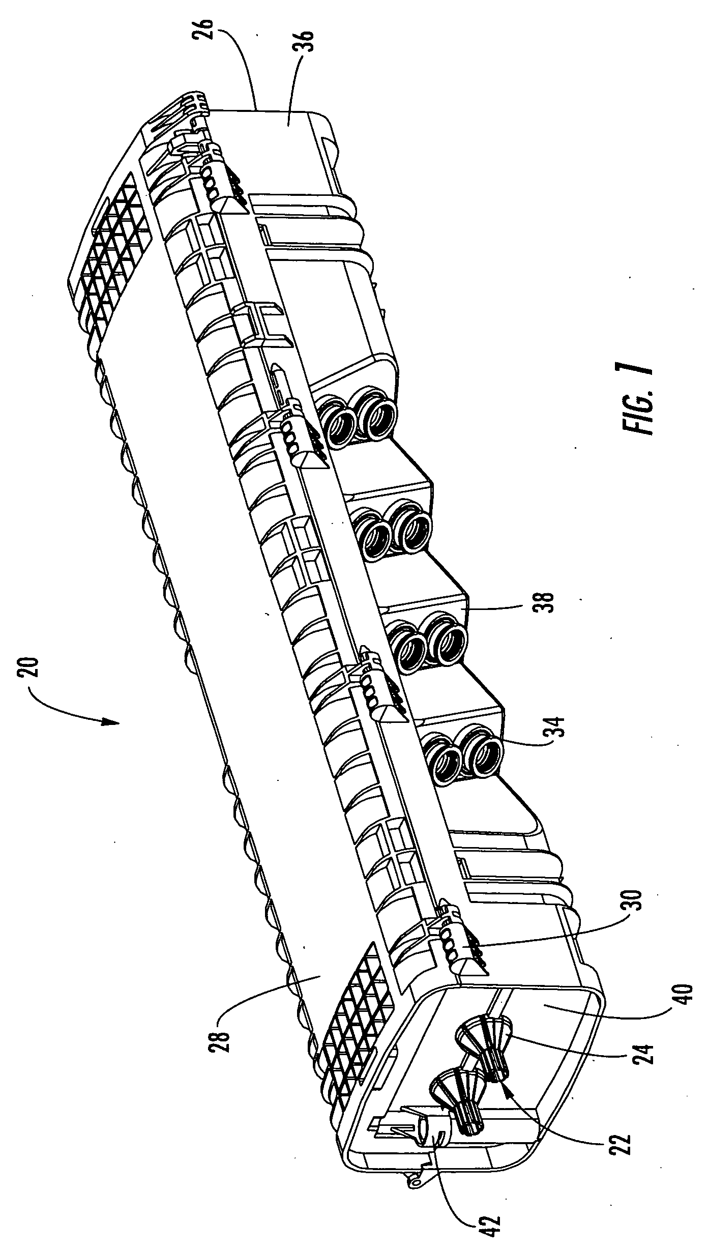
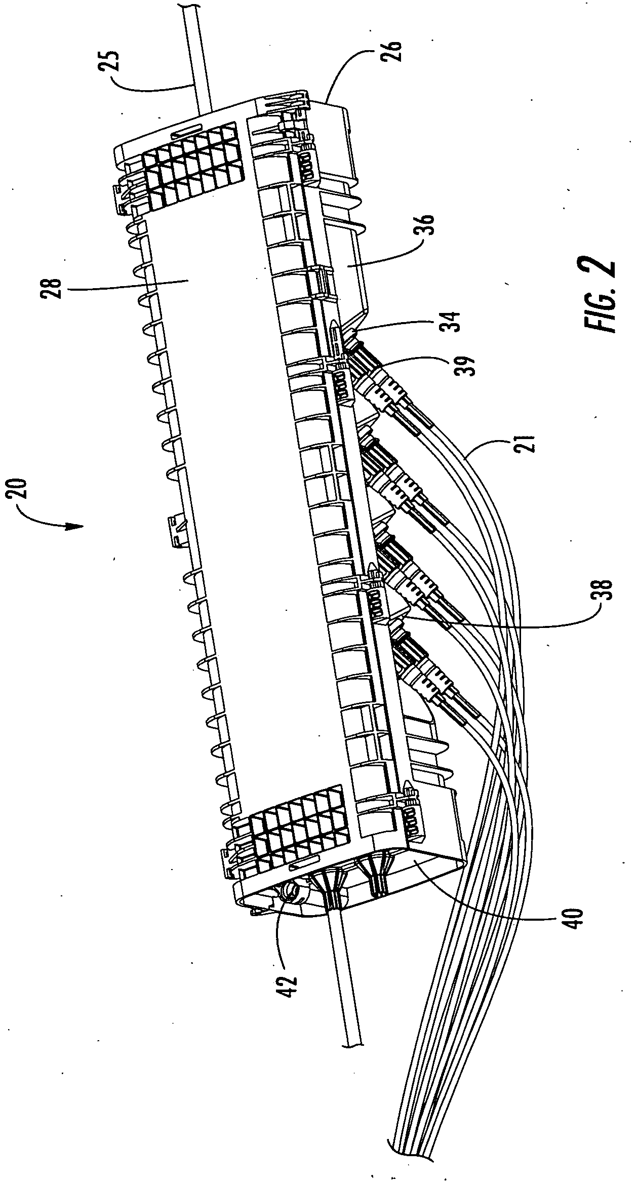
[0024] The present invention provides various embodiments of an optical connection closure having one or more connector ports located in an external wall of the closure for receiving connectorized optical fibers on the inside of the closure and pre-connectorized fiber optic drop cables on the outside of the closure. Each connector port may include a connector adapter sleeve disposed within the connector por...


PUM


Abstract

An optical connection closure has at least one connector port located within an external wall of the closure for receiving a connectorized optical fiber of a distribution cable on the inside of the closure and a pre-connectorized fiber optic drop cable on the outside of the closure. The closure includes a base, a cover affixed to the base and movable between a closed position and an opened position, and an end wall that defines at least a portion of at least one cable opening for receiving the distribution cable in a butt-type or a through-type closure configuration. The base and the cover define an interior cavity that optionally contains a splice tray for interconnecting the optical fiber of the distribution cable with a pigtail to create the connectorized optical fiber. The connector port may be located within an end wall, a bottom wall or a top wall of the closure.

Description

BACKGROUND OF THE INVENTION [0001] 1. Field of the Invention [0002] The present invention relates generally to enclosures deployed in fiber optic communications networks, and more specifically, to an optical connection closure having at least one connector port located in an external wall of the closure operable for receiving a connectorized optical fiber on the inside of the closure and a pre-connectorized fiber optic drop cable on the outside of the closure. [0003] 2. Description of the Related Art [0004] Optical fiber is increasingly being used for a variety of broadband applications including voice, video and data transmissions. As a result of the ever-increasing demand for broadband communications, fiber optic networks typically include a large number of mid-span access locations at which one or more optical fibers are branched from a distribution cable. These mid-span access locations provide a branch point from the distribution cable leading to an end user, commonly referred ...

Claims


Application Information

Patent Timeline
Patent Type & Authority Applications(United States)
IPC IPC(8): G02B6/38G02B6/44
CPCG02B6/445G02B6/3897
Inventor BATTEY, JENNIFER A.CASTONGUAY, GUYCLAPP, DONNIE R. JR.COX, TERRY D.MENKE, BRETT A.REAGAN, JASON B.VO, CHANH C.
Owner CORNING OPTICAL COMM LLC
Why Eureka
Try Eureka