
Particle counter for liquids

Inactive Publication Date: 2005-08-11
FACILITY MONITORING SYST
View PDF5 Cites 5 Cited by
  • Summary
  • Abstract
  • Description
  • Claims
  • Application Information

AI Technical Summary

Benefits of technology

[0010] The use of a glass tube facilitates the use of push on fittings for the sample cell for the supply and removal of liquid.

Problems solved by technology

The problem is that known liquid particle counters are complex and costly and are therefore not considered to be sufficiently cost-effective for water treatment installations and air conditioning systems.

Method used


Image

  • Particle counter for liquids
  • Particle counter for liquids

Examples


Embodiment Construction

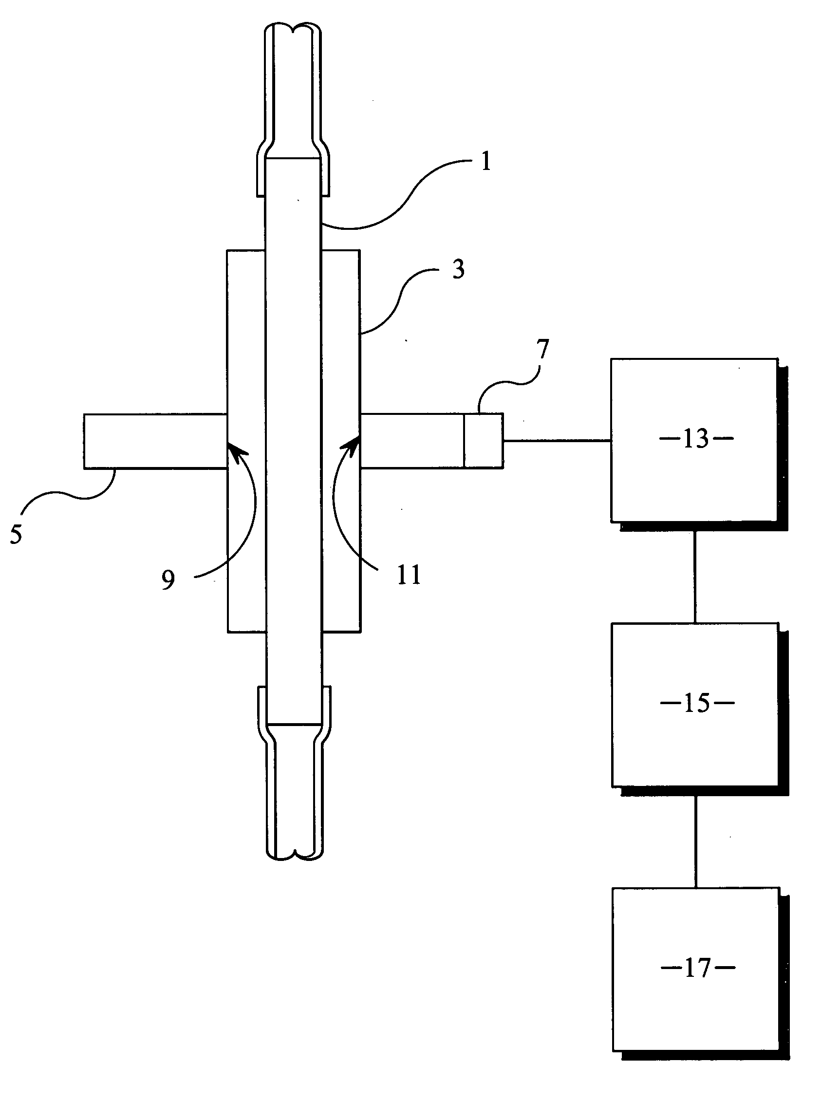
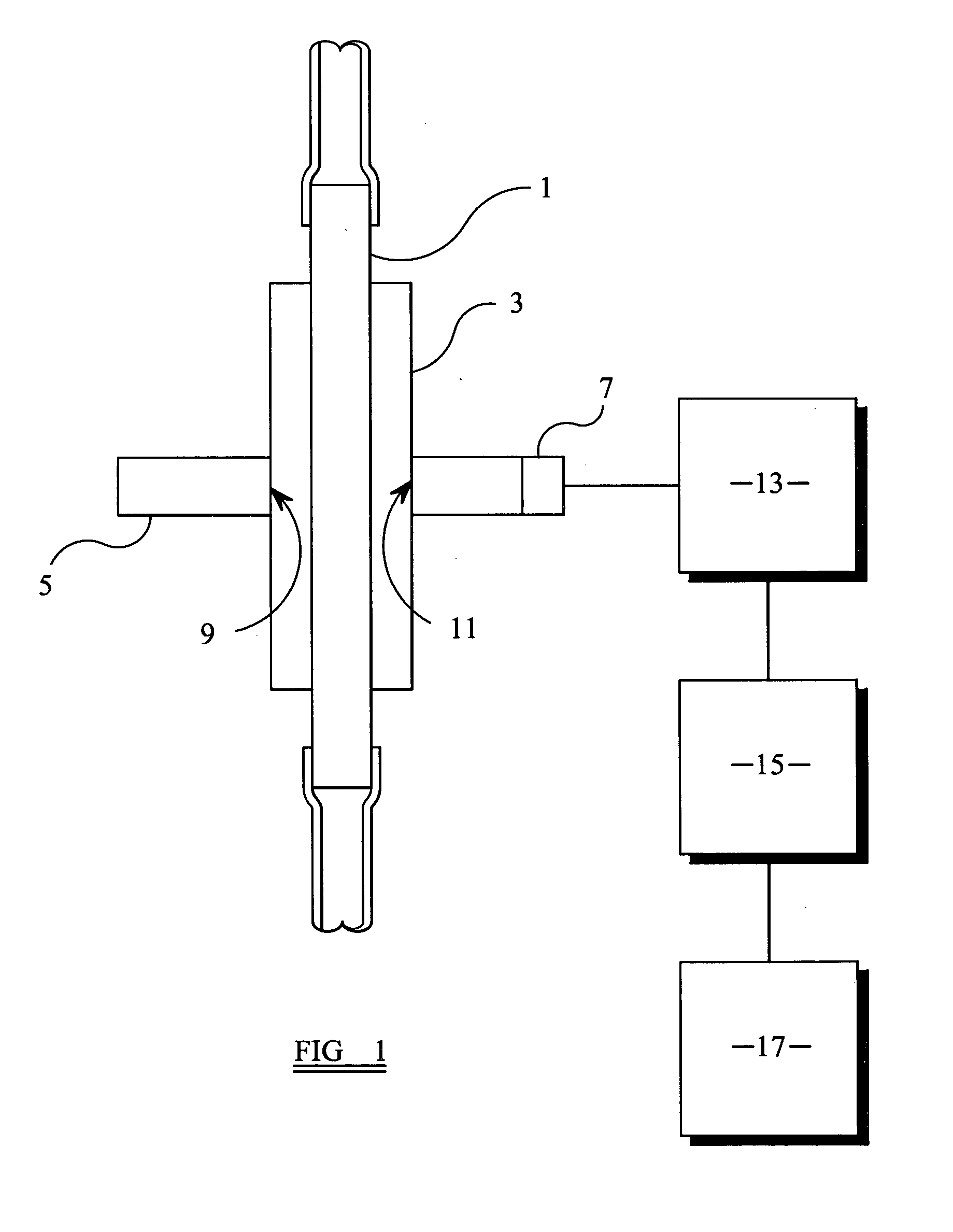
[0016] The liquid particle counter is shown in FIG. 1 in diagrammatic form and comprises a sample cell 1 which is made of conventional glass capillary tubing of substantially circular cross-section. In liquid counters it is standard practice to use a rectangular sample cell which is much more costly than glass tubing. It has generally been assumed that the sample cell must have planar faces which are perpendicular to the axis of a beam of light which, in use, passes through the sample cell. Surprisingly, we have found that when a small aperture is used the cylindrical surface of the sample cell appears to be substantially flat and perpendicular to the axis of the beam of light. The use of a cylindrical sample cell also offers the advantage over rectangular sample cells that push fit connections can be made thereby eliminating the need for costly connectors which are associated with connecting a rectangular sample cell to conventional cylindrical tubing. The glass tubing may have an ...


PUM


Abstract

A liquid particle counter includes an in situ light obscuration sensor (3). The sensor includes a sample cell (1) in the form of a glass tube of substantially circular cross-section for the passage of liquid, a light source (5) for directing a beam of light through the sample cell, and a photo-detector (7) for providing a signal representative of the amount of light passing through the sample cell (1). The signal is processed so as to produce an output (17) representative of a particle count.

Description

BACKGROUND TO THE INVENTION [0001] The detection, sizing and counting of particles in liquids, such as water, has been known for many years. The primary reason for counting particles in liquids is to be able to determine and control the levels of contamination in the liquid. For example, in the context of drinking water, particle counting is used to monitor the cleanliness of drinking water, with the presence of particles being taken to indicate the possible presence of bacteria and similar organisms. [0002] Particle counting has the benefit of providing very rapid results, but nevertheless cannot identify the nature of any particular particle. For example, a particle could be of an inert material or it could be biologically active. For safety, any particle is therefore considered to be biologically active. [0003] It takes several days to monitor drinking water for bacteria such as by microscopic examination of filtered samples incubated on agar plates. By this time it is too late t...

Claims


Application Information

Patent Timeline
IPC IPC(8): G01N15/14
CPCG01N15/1459G01N2015/1493G01N2015/1486
Inventor HILL, BARRINGTON JAMES
Owner FACILITY MONITORING SYST
Learn More