Method and apparatus for using a display associated with a dental kiln

a technology of display and kiln, which is applied in the direction of lighting and heating apparatus, teeth capping, furniture, etc., can solve the problems of misunderstanding or incorrect interpretation of the coding of the pertaining surface area, new dental restorations that don't exactly agree with the color of the tooth to be restored, and the probability of errors occurring, so as to reduce the probability of mistakes and correct the possibility of handwritten notes

Active Publication Date: 2005-08-11
IVOCLAR VIVADENT AG
View PDF10 Cites 15 Cited by
  • Summary
  • Abstract
  • Description
  • Claims
  • Application Information

AI Technical Summary

Benefits of technology

[0019] Pursuant to the invention it is expedient if the pertaining data is transmitted, together with the order, to a dental lab, in a suitable manner, such as, for example, per chip card, per e-mail, per diskette, or for example also by a CD that has been burned for this purpose. The direct spatial proximity of the indicator to the kiln ensures that the dental technician, especially during the firing, or the charging of the kiln, has the tooth that is to be restored in his or her field of vision, thereby significantly reducing the probability of mistakes occurring. The correctness of possible handwritten notes does not matter, since the dental camera, based upon appropriate color comparison, reliably delivers the desired colors for the restoration.

Problems solved by technology

Therefore there might always be the risk that the new dental restoration doesn't exactly agree with the color of the tooth to be restored, although the technician has used the right ceramic colors.
Despite this aid, the results of the restoration are frequently not satisfactory.
For example, there can also be misunderstandings or incorrect interpretations with regard to the coding of the pertaining surface areas, especially if the pertaining tooth colors are written down by the dentist in longhand.
In addition, a black and white expression makes it very difficult to assess the optical effect of the tooth that is to be restored, so that to this extent one must rely very heavily upon the experience not only of the dentist but also of the dental technician, which of course affects the result of the restoration.
There is also the danger that mistakes or mix-ups can occur, especially if, for example, a number of teeth are to be produced for the same patient, which teeth generally exhibit very little difference in shading.

Method used


Image

  • Method and apparatus for using a display associated with a dental kiln
  • Method and apparatus for using a display associated with a dental kiln
  • Method and apparatus for using a display associated with a dental kiln

Examples


Embodiment Construction

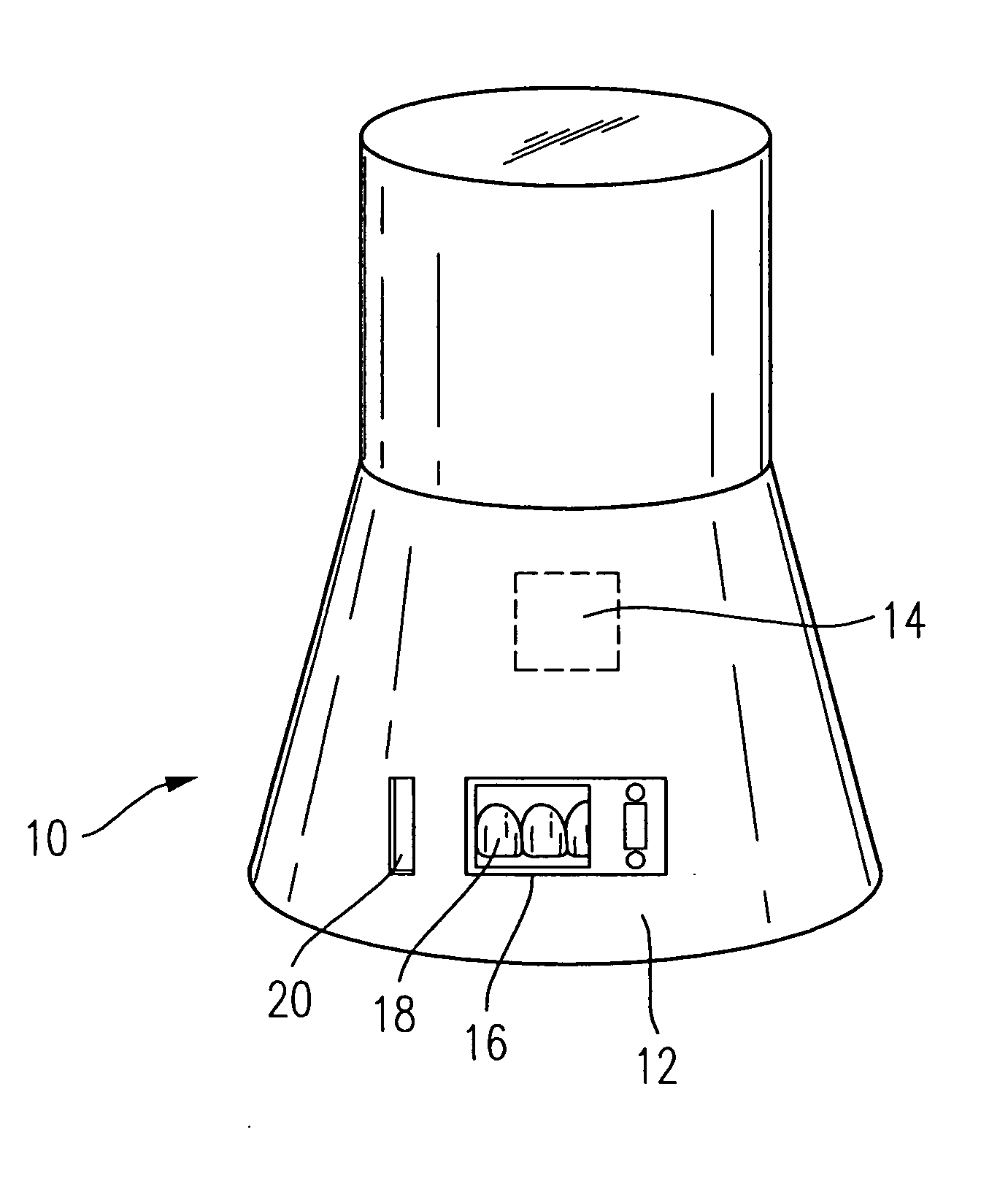
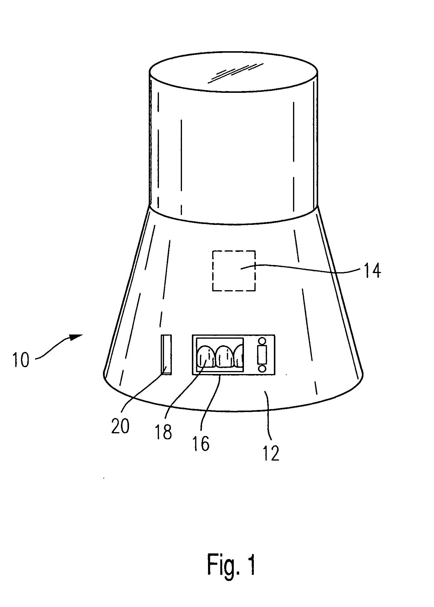
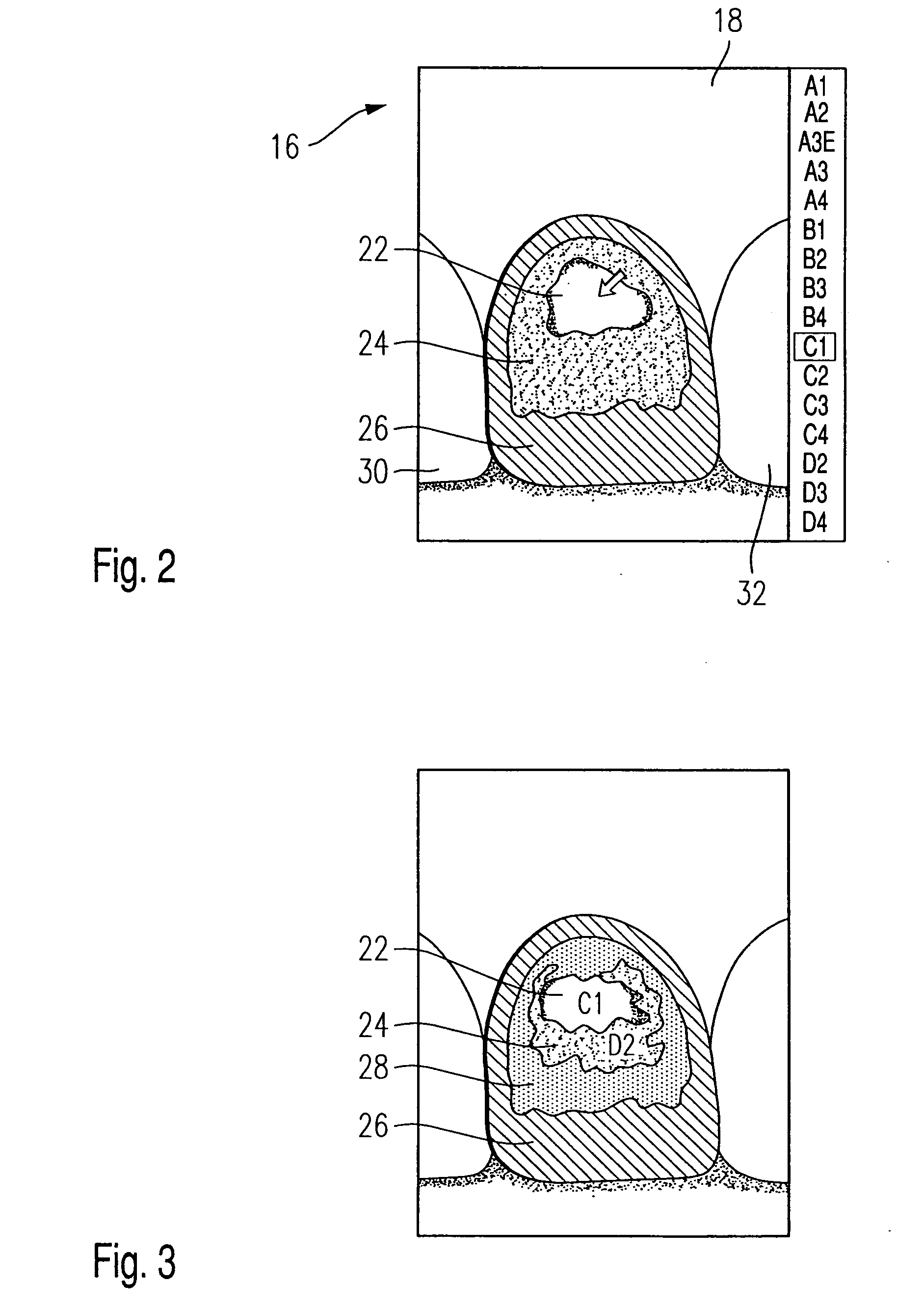
[0043] Referring now to the drawings in detail, the firing kiln or kiln 10 illustrated in FIG. 1 is provided with control elements 12 that act upon a schematically indicated control device 14. The control device serves, among other things, for the control of the firing curve pursuant to the set firing curves. The control device also makes available the information that can be visibly indicated for the dental technician on an inventive indicator 16. The indicator 16 shows the contours of a front tooth 18 and surface areas that pursuant to the invention are to be developed in a particular manner. The surface areas themselves are illustrated in FIGS. 2 and 3.

[0044] The kiln 10 is furthermore provided with a suitable input device. In the illustrated embodiment, the reading or input slot 20 of a chip card is illustrated, which is made available to the dental technician together with the order for the firing of the desired restoration.

[0045] It is to be understood that other types of da...


PUM


Abstract

An kiln for dental restoration components is provided, and comprises an indicator having an image screen for displaying information. The image screen is provided with at least two, and in particular at least three, surface areas with which optically distinguishable features, including colors, types and structures, can be represented. The surface areas together essentially form a front and / or side view of at least one tooth.

Description

CROSS-REFERENCE TO RELATED APPLICATIONS [0001] This application claims foreign priority benefits under 35 U.S.C. §119 from German patent application Ser. No. 10 2004 002 724.2 filed Jan. 19, 2004.TECHNICAL FIELD [0002] The present invention relates to a method and apparatus for using a display associated with a dental kiln, and more particularly to a dental kiln assembly used for firing dental restorations which assembly includes a kiln, a display associated with the kiln, a control circuit associated with the display, an input circuit associated with the control circuit for inputing data corresponding to an image of at least one tooth that is to be restored, or an adjacent tooth, and wherein the control circuit is able to process the data received from the input circuit and to create an image on said display of at least two, and in particular at least three, surface areas with which optically distinguishable features can be represented, the surface areas together essentially formin...

Claims


Application Information

Patent Timeline
Patent Type & Authority Applications(United States)
IPC IPC(8): A61C13/00A61C13/08A61C13/20F27B17/02F27D19/00F27D21/00F27D21/02G01J3/46G01J3/52
CPCA61C1/0015A61C13/20F27D21/02F27D19/00F27B17/025
Inventor GRUNENFELDER, ROBERTROHNER, GOTTFRIED
Owner IVOCLAR VIVADENT AG
Why Eureka
Try Eureka