Mobile terminal device

a terminal device and mobile technology, applied in the direction of casings/cabinets/drawers, casings/cabinets/drawers, instruments, etc., can solve the problems of deteriorating appearance, heat sinks that cannot be appropriately placed in bags or pockets, and can be exposed at the external protruding portion, so as to reduce heat accumulation

Inactive Publication Date: 2005-08-11
HITACHI LTD
View PDF20 Cites 35 Cited by
  • Summary
  • Abstract
  • Description
  • Claims
  • Application Information

AI Technical Summary

Benefits of technology

[0009] This invention can provide a mobile te...

Problems solved by technology

However, the invention of the aforementioned JP-A-2001-230578 has a problem that the heat sink is exposed at the external protruding portion and cannot be appropriately placed in a bag or a pocket.
Moreover, there is a case that this deteriorates the appearance.
Moreover, the invention of the aforementioned JP-A-2002-271049 has a problem that the area of the heat sink which can be exposed outside by opening a part of the case is relatively small and the heat radiation effect is limited.
Moreover, since the slide operation...

Method used


Image

  • Mobile terminal device
  • Mobile terminal device
  • Mobile terminal device

Examples


first embodiment

[0020] this invention will be described with reference to the drawings.

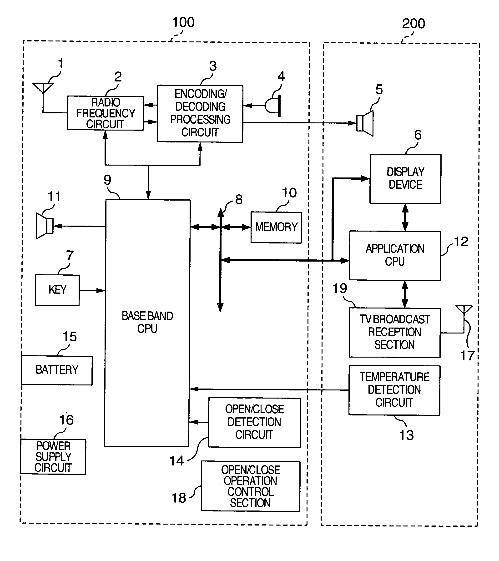
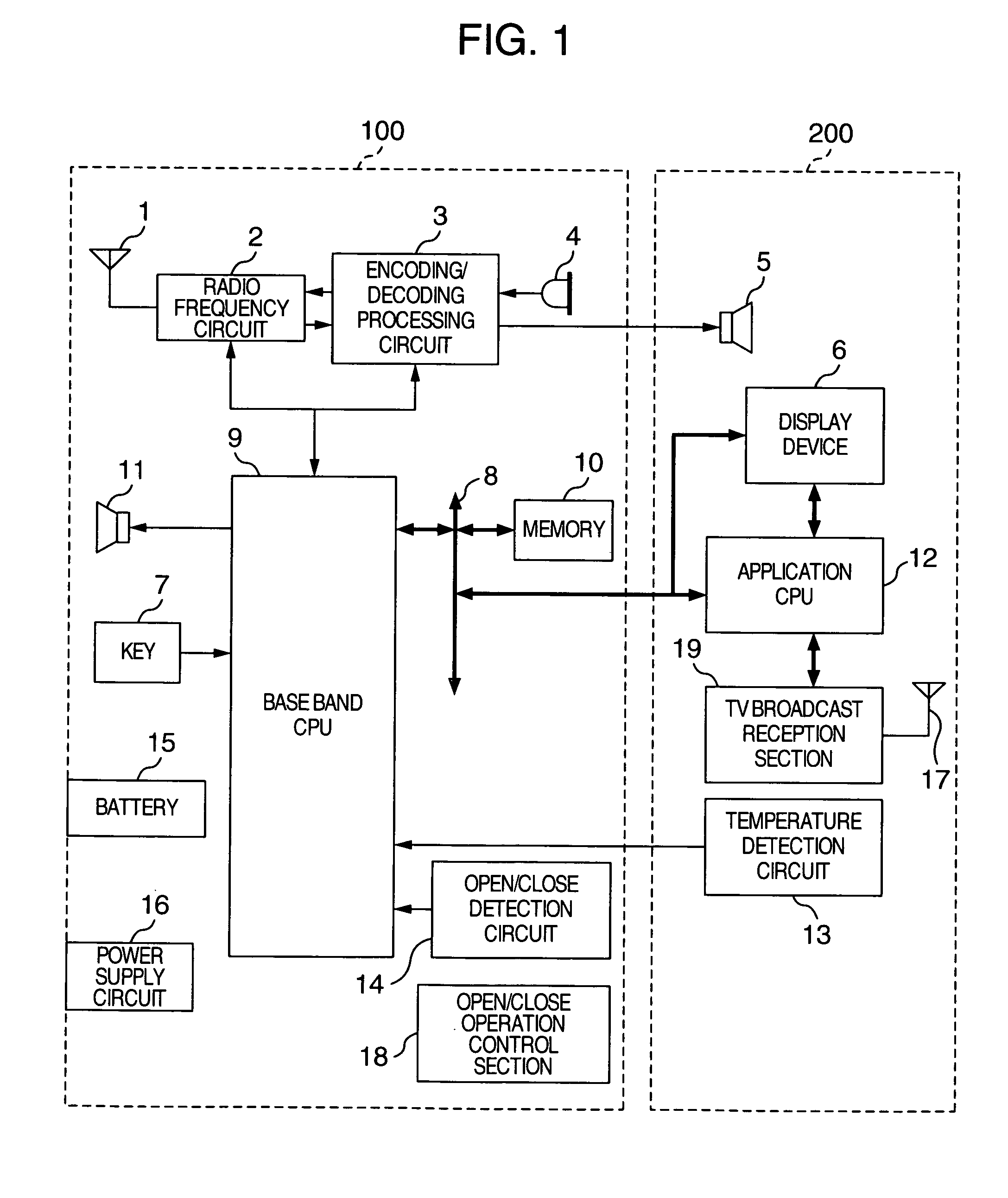
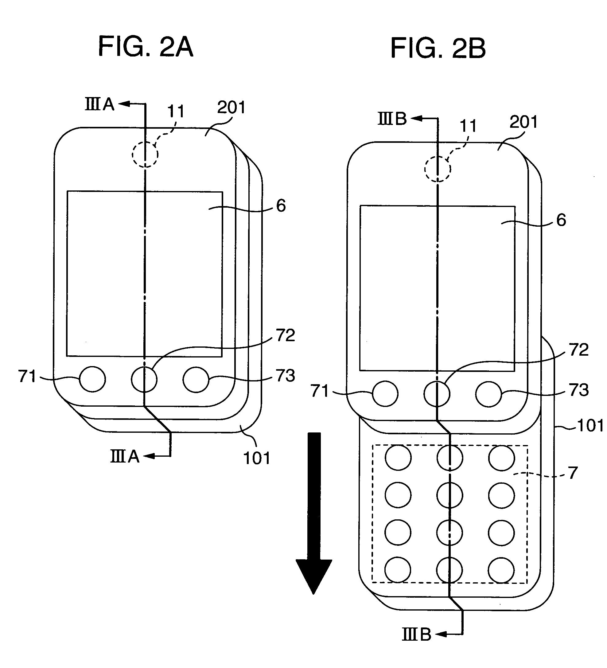
[0021]FIG. 1 is a block diagram showing configuration of a mobile telephone. In the figure, the mobile telephone includes an antenna 1, a radio frequency circuit 2, a code decoding circuit 3, a microphone 4, a receiver 5, a display device 6, a key 7, a CPU bus 8, a base band CPU 9, a memory 10, a loudspeaker 11, an application CPU 12, a temperature detection circuit 13, an open / close detection circuit 14, a battery 15, a power supply circuit 16, a TV broadcast reception antenna 17, an open / close operation control section 18, and a TV broadcast reception section (tuner) 19. A reference symbol 100 denotes a lower substrate and 200 denotes an upper substrate The upper substrate is mounted in the upper case and the lower substrate 100 is mounted in the lower case of the slide type mobile telephone shown in FIG. 2.

[0022] Hereinafter, each of the components will be described.

[0023] The antenna 1 receives an electric ...

third embodiment

[0076] Description will now be directed to a mobile telephone according to this invention.

[0077] In the aforementioned embodiment, the genre of the application which can be executed is limited by the open / close state of the set. In this embodiment, the operation frequency of the application CPU 12 is limited. Here, explanation will be given on the case that the operation frequency of the application CPU 12 is limited by reducing the image size treated.

[0078]FIGS. 8A to 8E are examples of screen display on the display device 6 when the moving picture is reproduced while the set is in the closed state. FIGS. 8A to 8E show the case for reproducing the “Pochi's dance” and the “Meow's rope-walking” stored as the moving picture file. FIGS. 8A to 8C are almost identical to the aforementioned embodiment except for that the “movie” is selected in FIG. 8C. In FIG. 8D, the image size of the “Pochi's dance” is 240 pixels in the lateral direction×320 pixels in the vertical direction while the i...


PUM


Abstract

A mobile terminal device comprises a first case including display unit, and a second case arranged so as to slide with respect to the first case and including input unit. The mobile terminal device further comprises a heat radiation member for radiating heat generated in the first case or in the second case. The heat radiation member has a surface area exposed outside which is changed in connection to the slide operation of the first and the second case.

Description

INCORPORATION BY REFERENCE [0001] The present application claims priority from Japanese application JP2004-028797 filed on Feb. 5, 2004, the content of which is hereby incorporated by reference into this application. BACKGROUND OF THE INVENTION [0002] This invention relates to a mobile terminal device. [0003] Conventionally, there has been suggested a mobile communication terminal having such a heat radiation structure that the heat generated from electronic parts is transferred by a member having a preferable thermal conductivity and radiated by a heat sink arranged outside (for example, see JP-A-2001-230578, page 3, FIG. 2). [0004] Moreover, there has been suggested a mobile electronic device having a case whose part can be slidably moved so as to expose the inner heat sink outside, thereby radiating the heat (for example, see JP-A-2002-271049, pp. 3-4, FIG. 3). [0005] However, the invention of the aforementioned JP-A-2001-230578 has a problem that the heat sink is exposed at the ...

Claims


Application Information

Patent Timeline
IPC IPC(8): G05D23/00H05K5/02G12B15/00H04M1/00H04M1/02H04M1/21H04Q7/20H05K7/14H05K7/18H05K7/20
CPCH04M1/0237H04M2250/12H04M1/72544H04M1/0245H04M1/72427
Inventor MASUDA, KOZOARAI, IKUYA
Owner HITACHI LTD
Why Eureka
Try Eureka