Low drag submerged asymmetric displacement lifting body

a technology of asymmetric displacement and lifting body, which is applied in the field of low drag submerged asymmetric displacement lifting body, can solve the problems of adverse effects, submerged bodies of marine vessels, and insufficient account of the free surface relative to the body shape in the prior art structure, so as to optimize the performance of the body

Active Publication Date: 2005-08-18
HULL SCI RES LLC
View PDF16 Cites 23 Cited by
  • Summary
  • Abstract
  • Description
  • Claims
  • Application Information

AI Technical Summary

Problems solved by technology

More specifically, as disclosed in U.S. Pat. No. 6,263,819, it was found that the submerged bodies of marine vessels, when operated at shallow submergence depths, such as is the case for SWAS and Mid-Foil vessels, can be adversely effected by the displacement of the free water surface caused by the body's volume and dynamic flow effects.
The interaction of that displacement of the free surface relative to the body's shape had not been adequately accounted for in the prior art structures.
It is believed that this inadequacy of existing prior art submerged bodies for marine vessels is the result of the fact that submerged and semi-submerged marine vessels have historically been designed to operate at great depths relative to their underwater body thickness, as with submarines or hydrofoils.
The displacement of water at the free surface by a submerged body is detrimental to a marine vessel's hydrodynamic performance with the impact varying as a function of the body's shape, submergence depth, speed and trim.
For example, the free surface effects can significantly reduce lift in the body or even cause negative lift (also referred to as sinkage) to occur.
Resistance to movement through the water by free surface effects is generally greater than if the submerged hull were operating at great depths; and pitch movements caused by the displacement of the free water surface vary with speed and create craft instability.
It was found that the performance of vessels using these shapes is adversely effected by the displacement of the free surface of the water above the bodies during operation of the vessel.

Method used


Image

  • Low drag submerged asymmetric displacement lifting body
  • Low drag submerged asymmetric displacement lifting body
  • Low drag submerged asymmetric displacement lifting body

Examples


Embodiment Construction

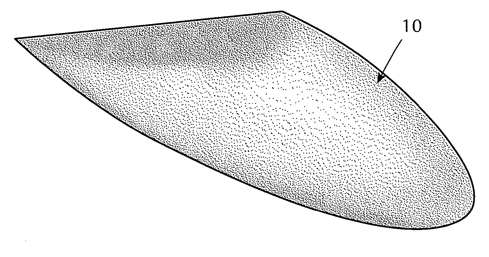
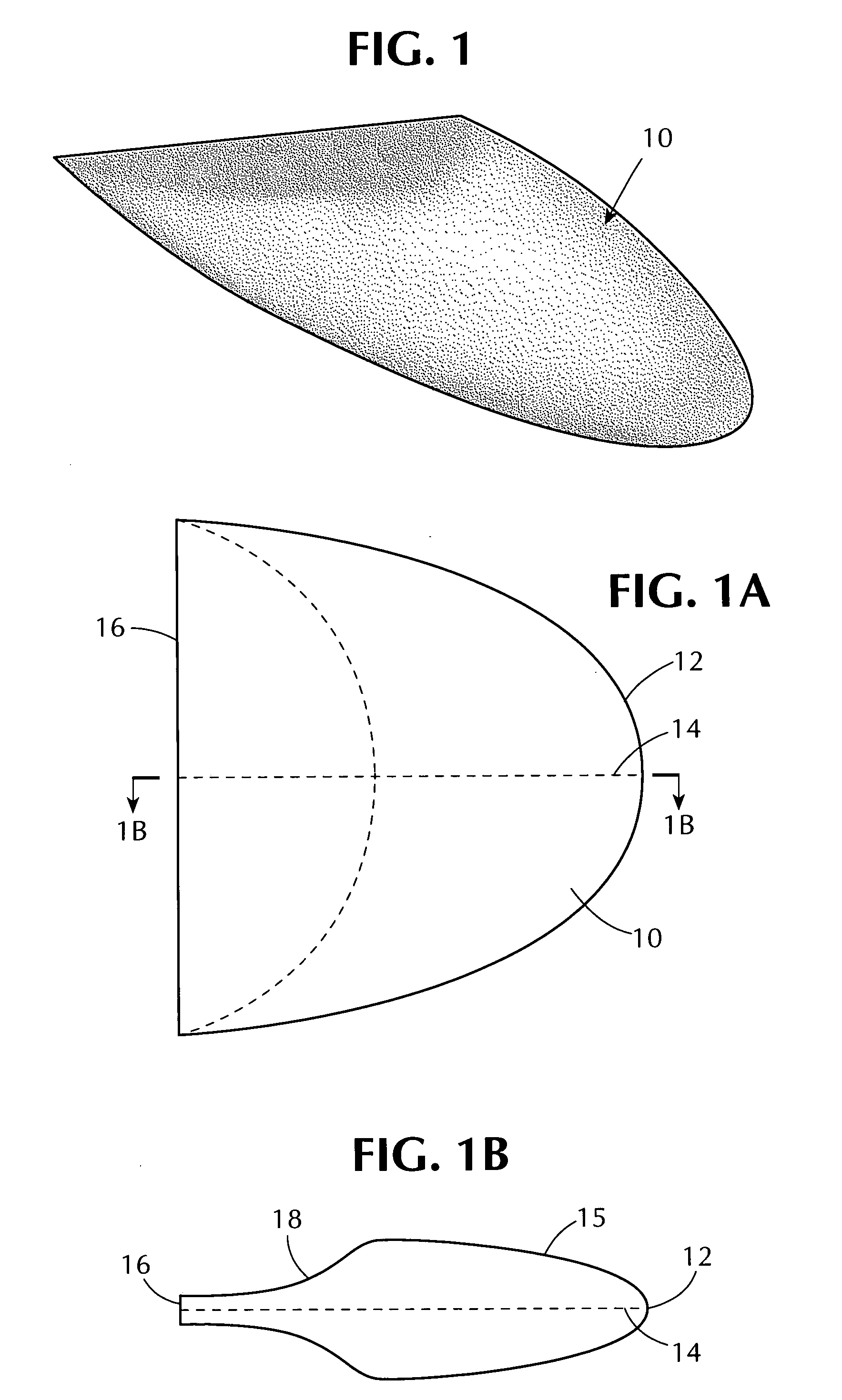
[0067] Referring now to the drawing in detail, FIG. 1 illustrates the basic hull form 10 of one embodiment of the invention described in U.S. Pat. No. 6,263,819, the disclosure of which is incorporated herein by reference. The lifting body hull 10 has a parabolic configuration in plan and a generally parabolic foil shape in longitudinal cross-section. This is illustrated more clearly in FIGS. 1A and 1B. As seen in FIG. 1A, hull 10 has a peripheral edge 12, also referred to herein as the leading edge of the hull, which defines the widest portion of the lifting body when viewed in plan. This edge is defined as a parabola substantially conforming to the conventional parabolic equation.

[0068] The shape of lifting body 10, in cross-section, is generally that of a parabola 15, as seen in FIG. 1B. The specific shape of the two parabolas 12 and 15 may vary generally as desired according to the size requirements of the vessel, and within certain ranges of length to thickness, and aspect rat...


PUM


Abstract

Low drag underwater submerged lifting bodies which can be used as underwater displacement portions of a vessel whose main hull is at sea level are asymmetrical and have improved lift to drag ratios. The lifting bodies have outer surfaces whose shapes are defined in plan and elevation by generally parabolic curves which are different on opposite sides of the lifting bodies.

Description

[0001] This application claims the benefit of U.S. Provisional Application No. 60 / 466,787, filed May 1, 2003.BACKGROUND OF THE INVENTION [0002] 1. Field of the Invention [0003] The present invention relates to ships and watercrafts having improved efficiency and seakeeping from underwater submerged displacement hull(s) attached to and part of a vessel that operates at sea level. [0004] 2. Background of the Invention [0005] In recent years interest in the use of small waterplane area ships (SWAS vessels) has substantially increased because such vessels have improved hydrodynamic stability, low water resistance and minimal ship motion. Generally such vessels have at least one waterline located below its design draft with a waterplane area that is significantly larger than the waterplane area at its design draft. One form of such vessel is known as a small waterplane area twin hull vessel (a SWATH vessel) which generally consists of two submerged hulls, originally formed of uniform cro...

Claims


Application Information

Patent Timeline
Patent Type & Authority Applications(United States)
IPC IPC(8): B63B1/00B63B1/10B63B1/12B63B1/24B63B1/40B63B39/00B63B39/06B63H5/16
CPCB63B1/107B63B1/12B63B1/248B63B1/40Y02T70/125B63B39/06B63B2001/126B63B2001/128B63H5/16B63B39/00Y02T70/10B63B1/24
Inventor LOUI, STEVENSHIMOZONO, GARYKEIPPER, TROY
Owner HULL SCI RES LLC
Why Eureka
Try Eureka