Eureka AIR delivers breakthrough ideas for toughest innovation challenges, trusted by R&D personnel around the world.

Lithium metal anode construction for seawater or air semi-fuel cells having flexible pouch packaging

a technology of lithium metal anode and semi-fuel cell, which is applied in the direction of cell components, cell components, jackets/cases materials, etc., can solve the problems of limited prior art cell sizes, lithium-air batteries do not utilize their full potential in energy density, and the limitations of relatively shallow depths of underwater lithium batteries, etc., to achieve higher water pressure and higher water pressure

Active Publication Date: 2008-05-01
MAX POWER FRANCE
View PDF7 Cites 44 Cited by
  • Summary
  • Abstract
  • Description
  • Claims
  • Application Information

AI Technical Summary

Benefits of technology

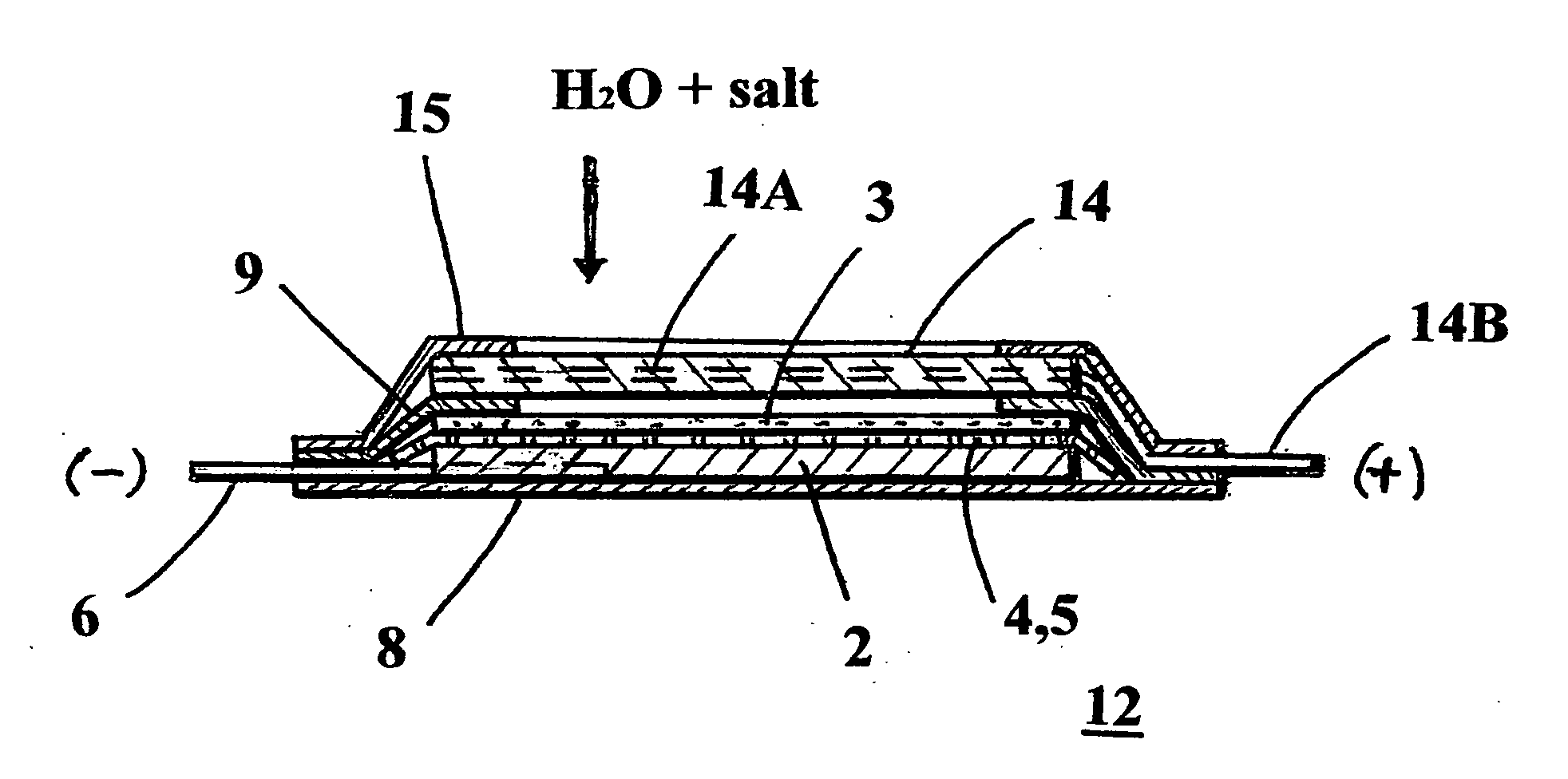
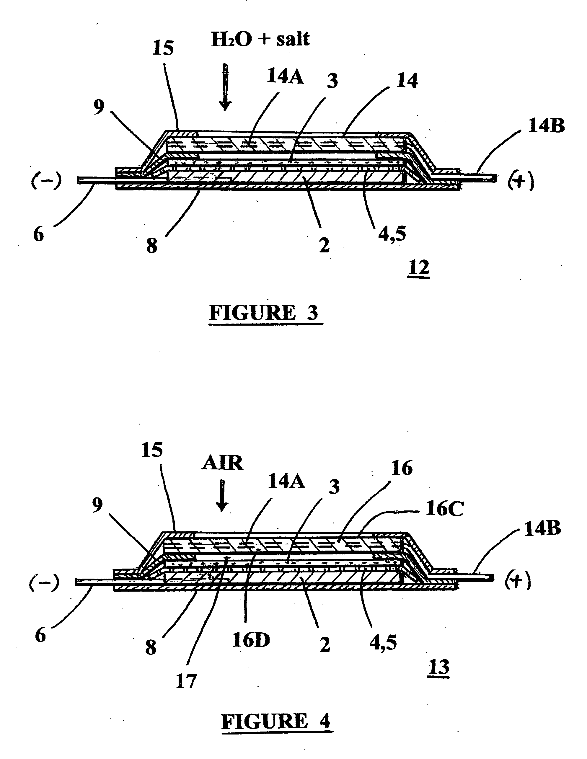
[0011]The underwater cells may be identically constructed except the aqueous H2SO4 or KOH electrolyte is replaced with seawater soaked into the cell cathode. In both applications, the cells may be constructed with a large area cathode, facing a plurality of several smaller anodes, electro-spun membranes, and ceramic separators, due to the size limitation of the ceramic separators, thus making a production of large lithium-seawater and lithium-air semi-fuel cells possible.
[0013]In case of lithium-air semi-fuel cells only, the cells may be also constructed differently, having the ceramic separator and the aqueous electrolyte removed and a polymeric, oxygen selective, hydrophobic gel or hydrophobic solid-state membrane added onto the outer side of the cathode. This membrane prevents evaporation of the non-aqueous electrolyte in the electro-spun membrane and in the inner side of the cathode, and permits oxygen to selectively enter the cathode. It also prevents any moisture in the air to enter the cell.

Problems solved by technology

However, the prior art underwater lithium batteries suffer from limitations of their use in relatively shallow depths, due to their low resistance to the high water pressure.
Prior art lithium-air batteries do not utilize their full potential in energy density, due to their relatively heavy packaging structures.
The prior art cell sizes are also limited by available ceramic layer, which can not be made in large sheets due to the brittleness of this material.

Method used


Image

  • Lithium metal anode construction for seawater or air semi-fuel cells having flexible pouch packaging
  • Lithium metal anode construction for seawater or air semi-fuel cells having flexible pouch packaging
  • Lithium metal anode construction for seawater or air semi-fuel cells having flexible pouch packaging

Examples


Embodiment Construction

[0034]When referring to the preferred embodiments, certain terminology will be utilized for the sake of clarity. Use of such terminology is intended to encompass not only the described embodiment, but also all technical equivalents which operate and function in substantially the same way to bring about the same results.

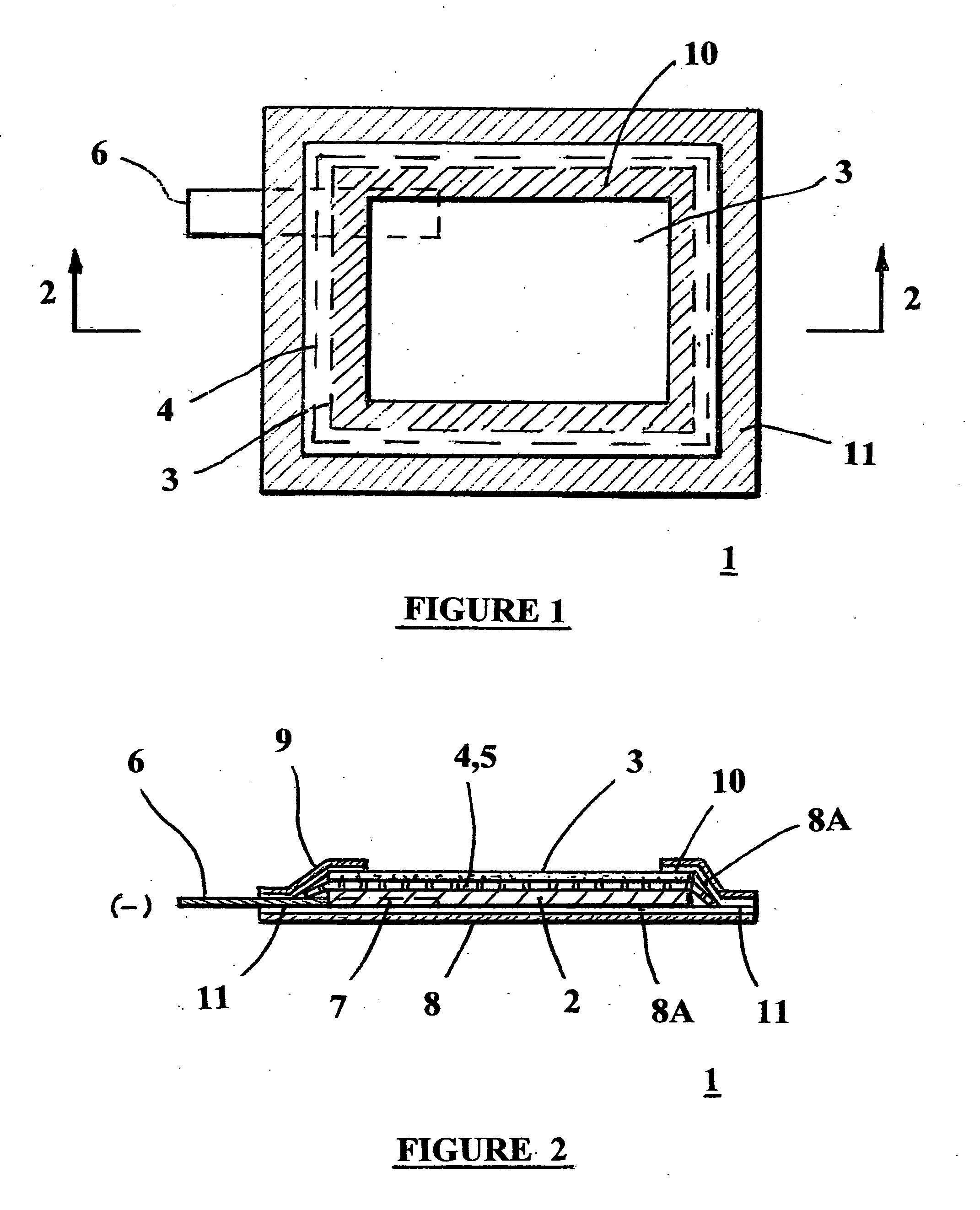
[0035]Lithium-seawater and lithium-air anodes usually comprise a lithium foil protected by a hard, moisture impermeable and sealed structure, which has on the active side ion conductive layers facing the cathode. The surrounding medium, such as seawater, or oxygen in air enters the porous cathode layer and results in an open circuit potential slightly higher than 3 volts against lithium.

[0036]Present invention employs new and novel anode packaging structure, which utilizes a compliant, flexible pouch enclosure heat welded to a glass-ceramic ion conductive layer facing the cathode, which provides for cell operation in greater depth of the ocean and also results in high...


PUM


Abstract

Lithium metal anode protection, and various semi-fuel cell constructions for use in deep, high pressure seawater or air media are provided. The described lithium semi-fuel cells achieve record high energy densities, due to the high energy density of lithium anode and the use of the cathode reactant from the surrounding media, which is not part of the cell weight, and the use of ultralight and flexible packaging materials. These features make the described semi-fuel cells the ideal choice for powering underwater and air vehicles.

Description

CROSS REFERENCE TO RELATED DOCUMENTS[0001]The subject matter of the invention is shown and described in the Disclosure Document of Ian Kowalczyk et al., Ser. No. 603,189 filed on Jul. 7, 2006 and entitled “Lithium Metal Anode Construction for Seawater or Air Semi-Fuel Cells Having Flexible Pouch Packaging.”BACKGROUND OF THE INVENTION[0002]1. Field of the Invention[0003]This invention pertains mostly to a lithium metal anode and cell construction having suitable multi-layer protection for use in high pressure lithium-seawater or lithium-air semi-fuel cells, while providing a very high energy density.[0004]2. Description of the Prior Art[0005]Lithium-water and lithium-air primary batteries are the batteries of choice for various military applications, like unmanned underwater vehicles and unmanned air vehicles, due to their record high practical energy densities (1000 Wh / kg). However, the prior art underwater lithium batteries suffer from limitations of their use in relatively shallow...

Claims


Application Information

Patent Timeline
IPC IPC(8): H01M2/02H01M4/40H01M6/34H01M50/119H01M50/121H01M50/124
CPCH01M2/0275H01M2/0277H01M2/0285H01M2/0287Y02E60/122H01M4/134H01M12/04H01M12/06H01M4/06Y02E60/10H01M50/124H01M50/121H01M50/119
Inventor KOWALCZYK, IANEPPLEY, WILLIAMSALOMON, MARKCHUA, DAVIDMEYER, BENJAMIN
Owner MAX POWER FRANCE
Why Eureka
Eureka Blog
Learn More