Underwater releaser

A releaser, seawater technology, applied in underwater operation equipment, transportation and packaging, ships, etc., can solve the safety problems of operators and equipment to be recovered, it is difficult to ensure long-term high reliability, watertightness, and consumables costs. Achieve the effect of avoiding normal and timely release, large bearing capacity, and high watertight reliability

Inactive Publication Date: 2008-12-24
HARBIN ENG UNIV
View PDF1 Cites 44 Cited by
  • Summary
  • Abstract
  • Description
  • Claims
  • Application Information

AI Technical Summary

Problems solved by technology

However, the blasting releaser has fatal disadvantages: during the use of the releaser, there are serious safety problems for the operator and the equipment to be recovered; in addition, the blasting releaser needs to replace the blasting parts every time, which has the cost of consumables and is inconvenient to operate
Therefore, the practice of using non-corrosion-resistant magnetic steel bolts is generally unacceptable
In addition, in the detailed discussion of this invention, the seal between the magnetic steel bolt and the pressure-resistant cabin it passes through is an "O"-shaped sealing ring. In a deep-water high-pressure environment, it is difficult to adopt such a sealing method. Watertight for long-term high reliability, similar to problems with mechanically driven releases
[0015] 2. The mechanical mechanism outside the pressure chamber is completely exposed to seawater, such a design will cause serious problems
This is also the Achilles heel of its force amplification mechanism

Method used


Image

  • Underwater releaser
  • Underwater releaser
  • Underwater releaser

Examples


Embodiment Construction

[0035] The present invention is described in more detail below in conjunction with accompanying drawing example:

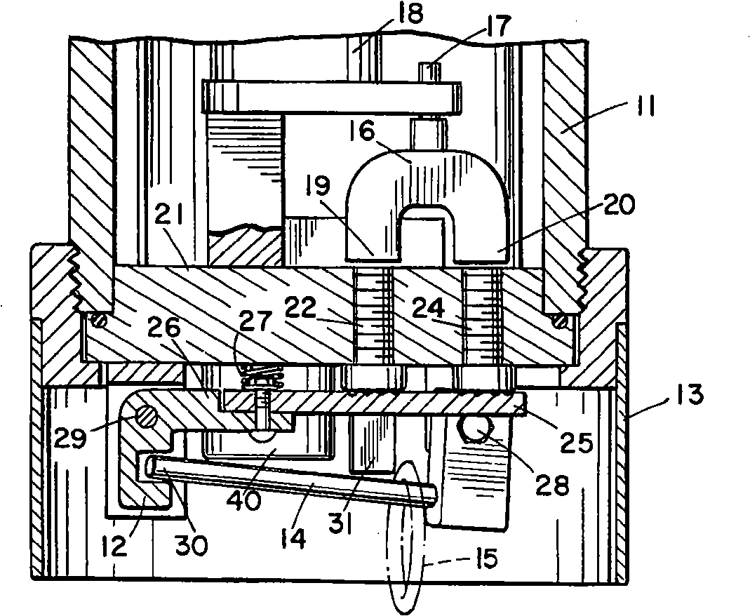
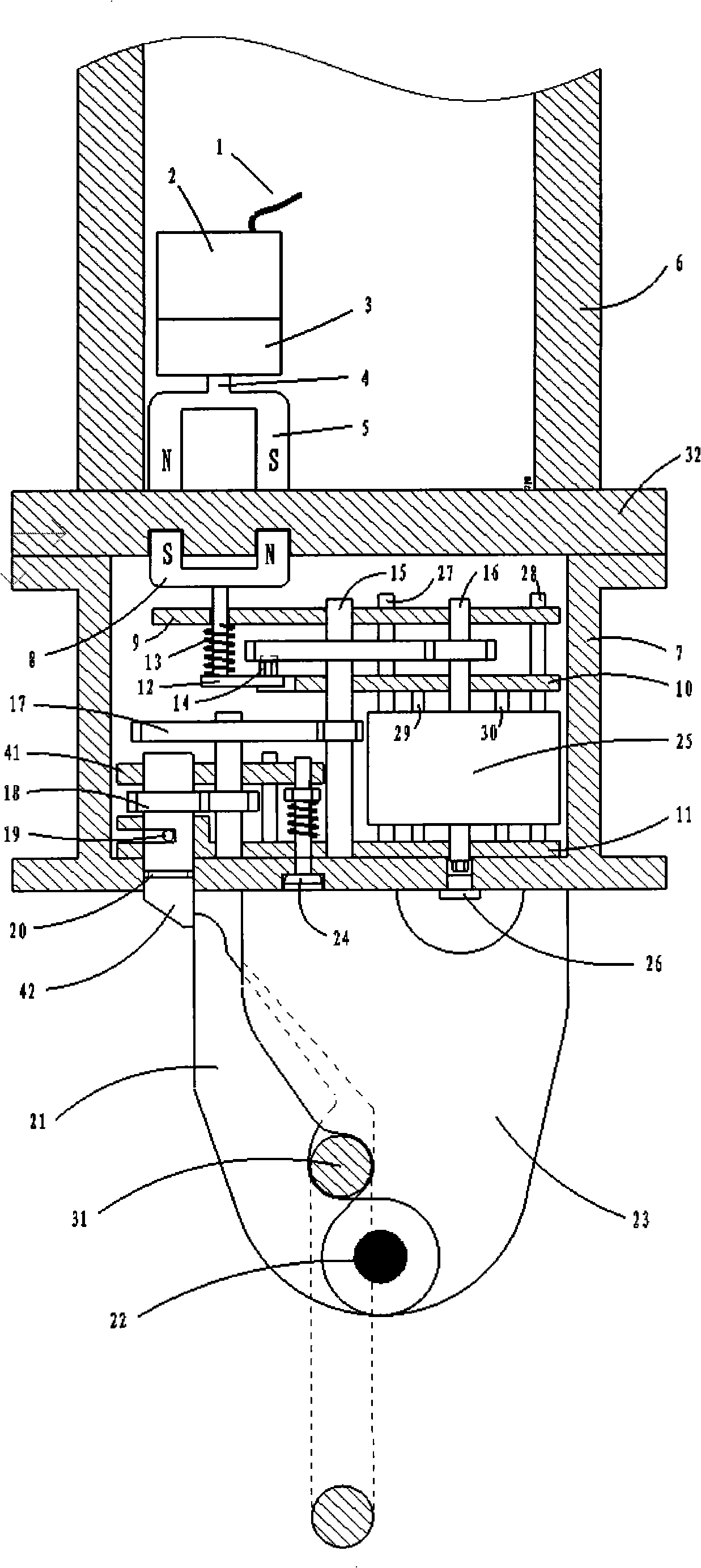
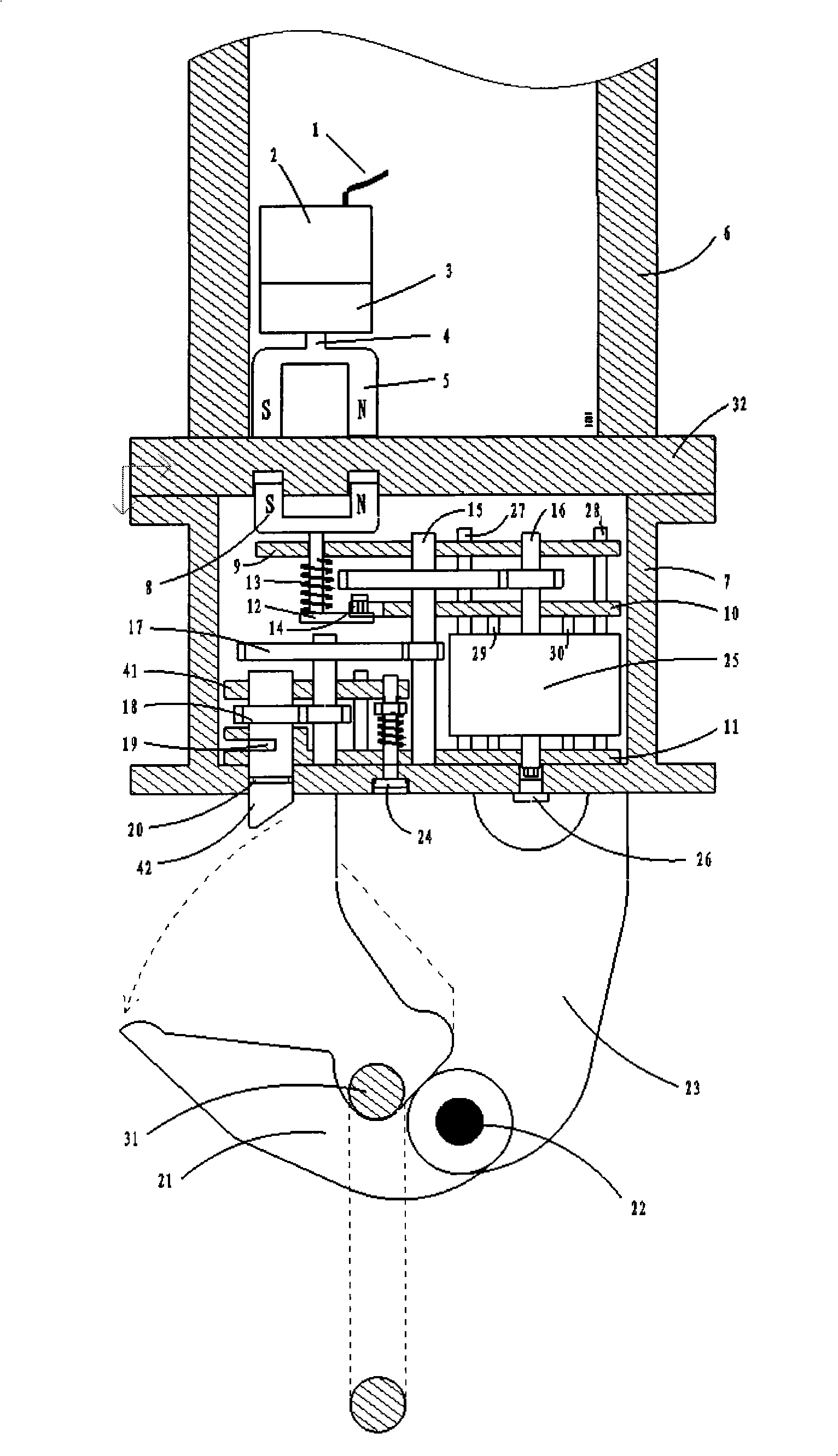
[0036] The underwater release device of the present invention is composed of eight parts: an electric part, a trigger mechanism, an energy storage mechanism, a deceleration mechanism, a two-way overflow mechanism, a dynamic sealing transmission mechanism and a release arm.

[0037] combine figure 2 . The electric part is located in the pressure chamber, and consists of control wires and cables 1, a DC motor 2, a reducer 3, a connecting shaft 4 and a first "U"-shaped magnetic steel 5. The axis of the connecting shaft 4 is perpendicular to the lower bottom plate 32 of the pressure chamber. The isolation cabin 7 and the lower bottom plate 32 jointly form a seawater isolation cabin section. The seawater isolation compartment is equipped with a two-way overflow mechanism 24, combined with Figure 4 , 33 is a threaded stainless steel bolt, and 34 is a watertight wa...


PUM


Abstract

The invention provides an underwater releaser, consisting of an electromotion part, a trigger mechanism, an energy storage mechanism, a speed reduction mechanism, a bidirectional overflow mechanism, a dynamic sealing transmission mechanism and a releasing arm, wherein the electromotion part is positioned inside a pressure-resistant cabin; a lower bottom plate of the pressure-resistant cabin is connected with an isolating cabin so as to jointly form a seawater isolating cabin segment in a circle; the seawater isolating cabin segment is provided with the bidirectional overflow mechanism; and the trigger mechanism, the energy storage mechanism and the speed reduction mechanism are all arranged inside the seawater isolating cabin segment. The underwater releaser adopts the design of combining two blocks of U-shaped magnetic steel, ensuring that the maximum trigger power is close to the scalar sum of the gravitational force and repulsive force between the U-shaped magnetic steel; by using a plane volute spring to store energy and using a gear set to reduce speed, the underwater releaser can provide great releasing power; a seawater isolating cabin is built through the bidirectional overflow design, which avoids seawater impact and the adverse effect of marine organisms; through a rotary unhooking mechanism, the releaser can have greater bearing capacity. The underwater releaser is not only better in watertight reliability, but also can work underwater for a long period of time without replacing components.

Description

(1) Technical field [0001] The invention relates to the mechanical part of an acoustic release. (2) Background technology [0002] An acoustic release generally consists of two parts, an electronic part and a mechanical part. The electronic part includes the underwater acoustic transducer part for acoustic-electric conversion and the circuit part for electric signal shaping and detection. The mechanical part executes the release action under the control of the circuit part. The invention pertains to the mechanical part of an acoustic release. [0003] People have a long history of research on underwater acoustic releasers, and some well-known foreign underwater equipment development companies also have model products for sale. The existing acoustic releasers can be roughly divided into four types according to different working principles: explosive type, fuse type, mechanical transmission type and magnetic type. [0004] The working principle of the blasting releaser is ...

Claims


Application Information

Patent Timeline
Patent Type & Authority Applications(China)
IPC IPC(8): B63C11/52
Inventor 王大成夏冬曾武李晔
Owner HARBIN ENG UNIV
Why Eureka
Try Eureka