Motorcycle engine guard with retractable footrests

Inactive Publication Date: 2005-08-18
LINDBY PER
View PDF17 Cites 10 Cited by
  • Summary
  • Abstract
  • Description
  • Claims
  • Application Information

AI Technical Summary

Benefits of technology

[0008] The present invention provides a strong engine guard of forged steel that protrudes from the side of a motorcycle immediately in front of the engine and behind the front wheel strut. This guard is designed to not bend or collapse, and to protect each side of the ‘cycle engine. In addition, the present invention is specially designed to serve as a footrest for the operator in two places. First, friction strips are imbedded or attached to the guard on either side in the protruding area most convenient for the operator's feet placement. Second, a foot peg is provided on each side, which pegs are flattened on the side facing the driver and may be pivotable from the engine guard such that the operator has the option of extending the pegs or folding them into the guard. The shape of the engine guard has been specially designed to be attractive to the operator, and the engine guard is chrome-coated.
[0010] Another object of the present invention is to provide an engine guard that is strong enough to resist bending or collapsing under the weight of the motorcycle in a slip or fall, or in an accident.
[0011] Still another object of the present invention is to provide an engine guard that will help protect the motorcycle engine and body from scratches and dents when the motorcycle is laid on its side.
[0012] Yet another object of the present invention is to provide an embodiment of the invention that will enhance the visual appearance of the motorcycle.
[0013] A further object of the present invention is to provide two footrests in two different locations for the comfort of the operator.
[0014] A further object of the present invention is to provide footrests that can be closed up to the bar of the engine guard to retain the integrity of the shape of the bar, and keep it attractive to operators and onlookers.

Problems solved by technology

Motorcycle engines are typically uncovered along the sides, and therefore exposed to possible damage.
Most manufacturers provide a bar or other guard to lessen the risk of damage, but such bars or guards are not attractive, are inconvenient for the placement of the rider's legs and feet, and are placed or shaped in such a way as to fail to adequately protect against damage from the side.
The difficulty with the prior art is that it requires additional parts and accessories to be added to a motorcycle.
However, the more parts that are added to a cycle, the more weight the cycle must carry with some resulting decrease in performance, plus the more parts there are subject to deterioration and breakage.

Method used


Image

  • Motorcycle engine guard with retractable footrests
  • Motorcycle engine guard with retractable footrests
  • Motorcycle engine guard with retractable footrests

Examples


Embodiment Construction

[0026] Detailed descriptions of the preferred embodiment are provided herein. It is to be understood, however, that the present invention may be embodied in various forms. Therefore, specific details disclosed herein are not to be interpreted as limiting, but rather as a basis for the claims and as representative basis for teaching one skilled in the art to employ the present invention in virtually any appropriately detailed system, structure, or manner. The drawings constitute a part of this specification and include exemplary embodiments to the invention, which may be embodied in various forms. It is to be understood that in some instances various aspects of the invention may be shown exaggerated or enlarged to facilitate an understanding of the invention.

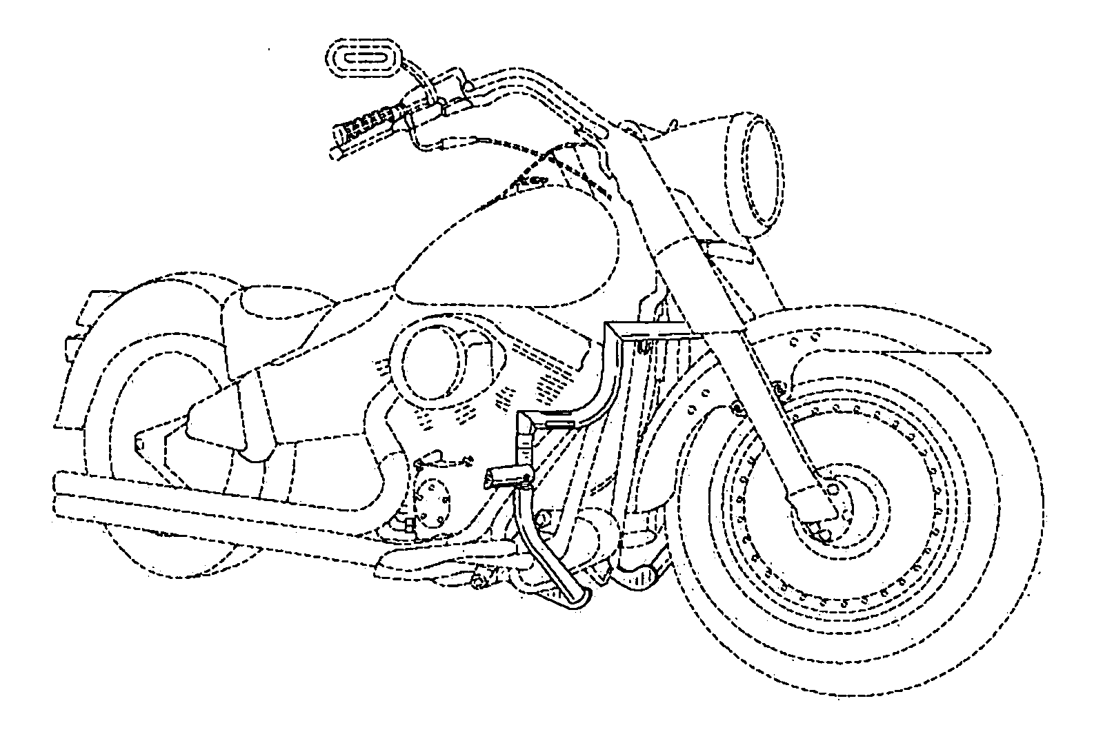
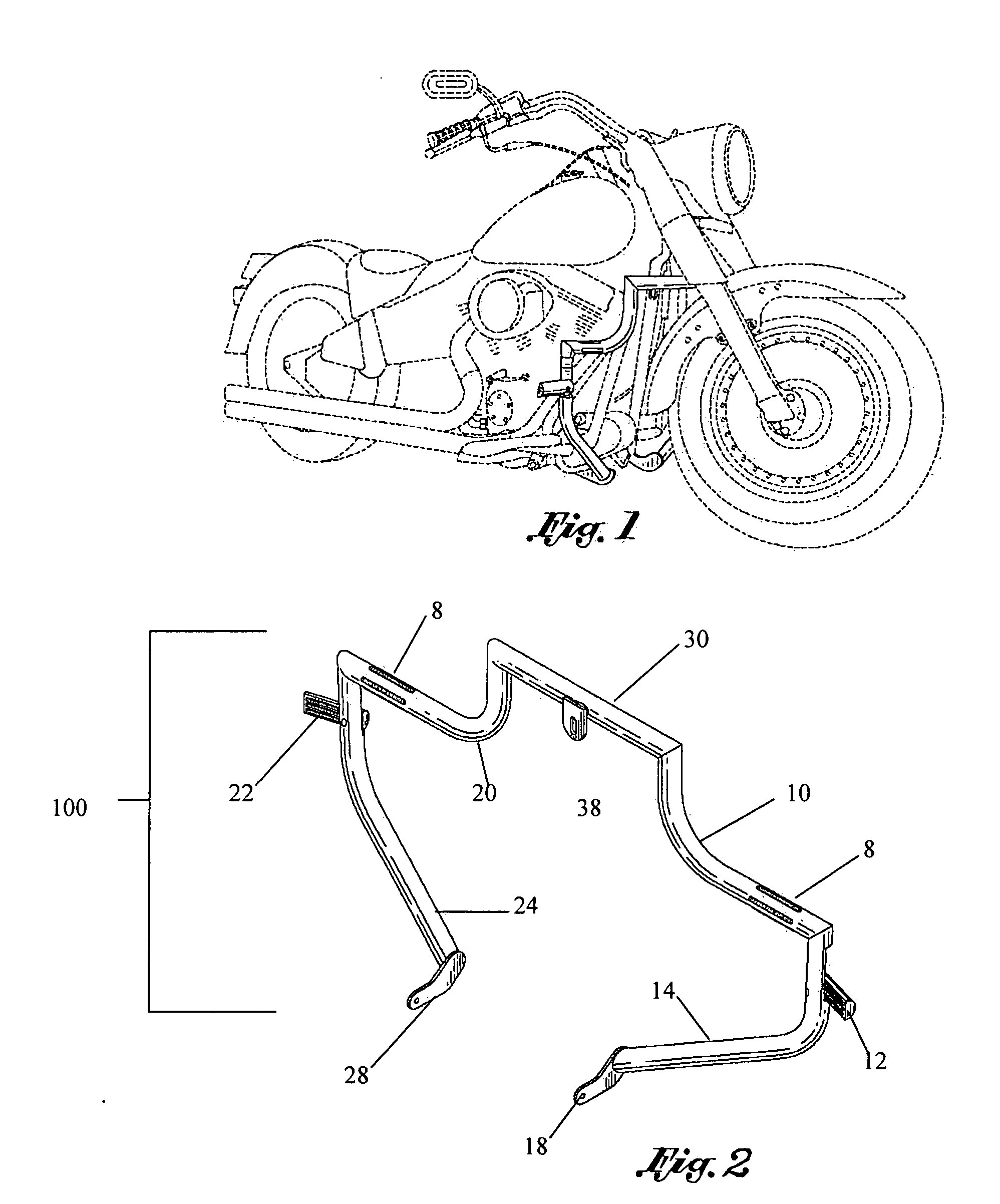
[0027]FIG. 1 shows a perspective view of a preferred embodiment of the present invention 100 as attached to a motorcycle. The motorcycle itself is not part of the current invention, and is therefore illustrated in broken lines. ...


PUM


Abstract

The invention herein described is a motorcycle guard with retractable footrests. The guard is mounted to the outside of the engine of a motorcycle. The footrests are extended for use, and retracted when no longer needed. A mechanism is installed to prevent over-extension of the footrests.

Description

CROSS-REFERENCE TO PRIOR APPLICATIONS [0001] This application describes the invention portrayed in design patent application 29 / 193,547 filed on Nov. 11, 2003. FIELD OF THE INVENTION [0002] This invention relates to motorcycle accessories, and more particularly to engine guards with retractable footrests. DESCRIPTION OF THE PRIOR ART [0003] The engine on a motorcycle is commonly placed toward the front of the vehicle, behind the front wheel struts and forward of the seat. Motorcycle engines are typically uncovered along the sides, and therefore exposed to possible damage. Most manufacturers provide a bar or other guard to lessen the risk of damage, but such bars or guards are not attractive, are inconvenient for the placement of the rider's legs and feet, and are placed or shaped in such a way as to fail to adequately protect against damage from the side. [0004] Some prior art teaches engine guards that combine with other functions for comfort of the operator. For example, U.S. Pat....

Claims


Application Information

Patent Timeline
IPC IPC(8): B62D61/02B62J25/00B62J27/00B62K27/00
CPCB62J25/00Y10T74/20918B62J27/00B62J25/06B62J27/30
Inventor LINDBY, PER
Owner LINDBY PER
Why Eureka
Try Eureka