
Communication system, communication receiving device and communication terminal in the system

a communication system and communication terminal technology, applied in the field of communication systems, can solve the problems of screen flicker, varied receivable channels, and difficulty in enjoying watching television on the mobile object comfortably, and achieve the effect of improving the orbital elements

Inactive Publication Date: 2005-08-18
MAEDA TOSHIHIDE +7
View PDF25 Cites 10 Cited by
  • Summary
  • Abstract
  • Description
  • Claims
  • Application Information

AI Technical Summary

Benefits of technology

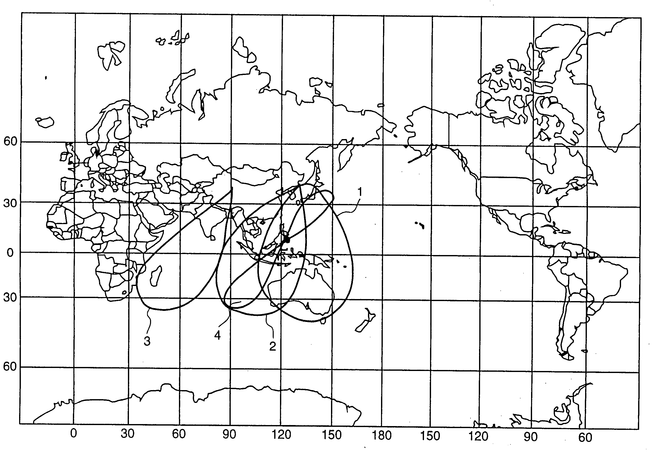
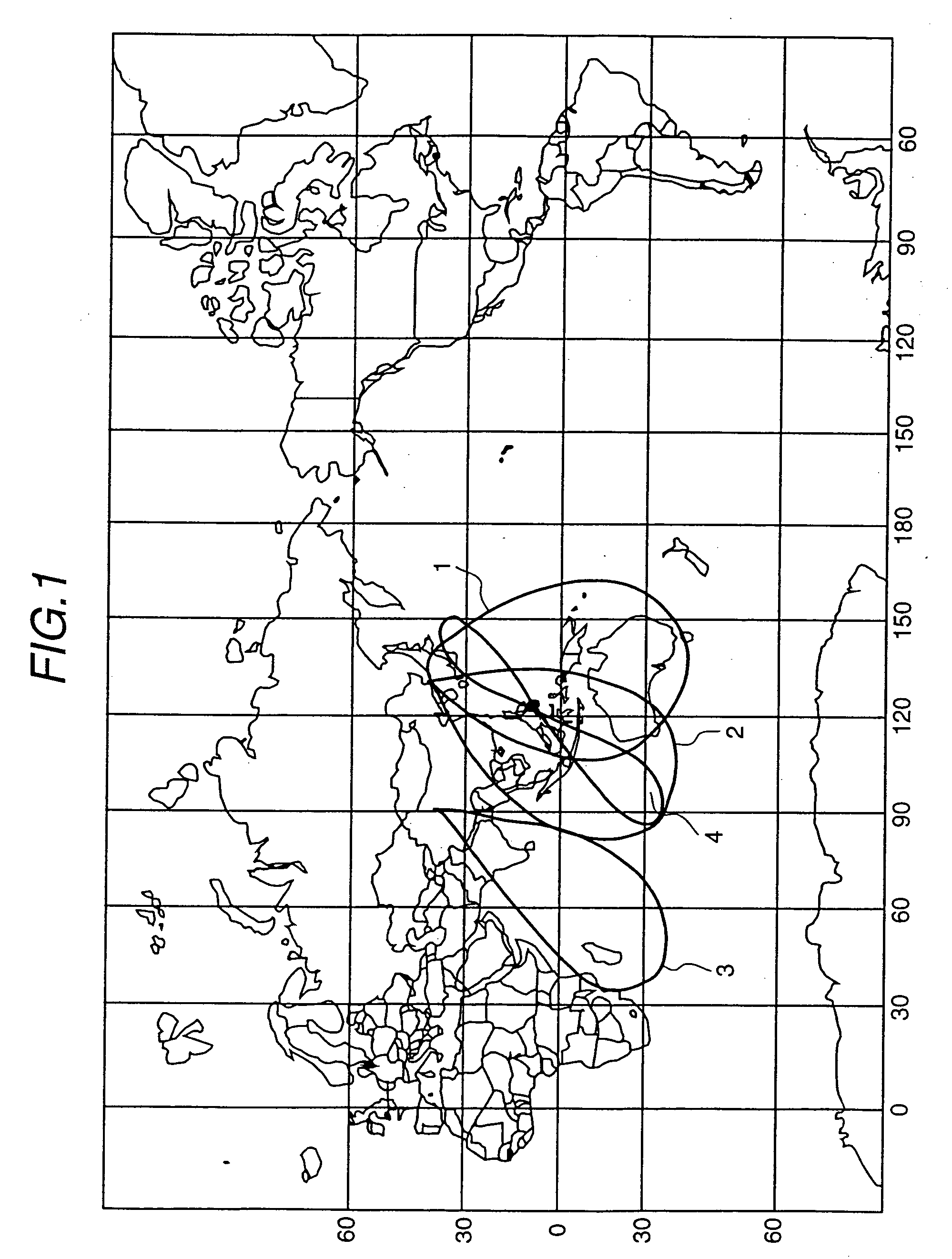
[0033] In order to solve the above problems, the present invention improves the orbital elements proposed in Japanese Patent Application Laid-Open No.11-34996 from the viewpoint of “communication with ground”. An object of the present invention is to set more effective ranges of orbital elements within the specified service area of Japanese territory.
[0034] Although an object of the present invention is to individually solve the problems described the above items (a), (b) and (c), the object is also to solve combinations of the items (a), (b) and (c), or all of the items (a), (b) and (c) at a time. Another object of the present invention is to provide a method of deriving orbital elements of artificial satellites capable of making mobile communication and mobile broadcast easy to the specified area of Japanese territory using a plurality of artificial satellites by solving the items (a), (b) and (c) together, and at the same time to express the orbital elements suitable for the Japanese territory by limiting the ranges.

Problems solved by technology

In the past, when a television broadcast was tried to receive in a mobile object such as a vehicle, there were problems in that the picture came out badly in an area far from a broadcasting facility of a television station, that screen flicker occurred even at a place near the broadcasting facility of the television station, and that receivable channel varied by moving.
When a television broadcast from a communication and broadcast satellite on a stationary orbit was received on the mobile object, it was difficult to comfortably enjoy watching television on the mobile object because the electromagnetic wave was frequently shielded by artificial structures such as buildings, trees and natural geographical features.
Transmission of a large volume of data such as images from a mobile object such as an ambulance can not be performed by an existing ground communication infrastructure and an existing communication satellite.

Method used


Image

  • Communication system, communication receiving device and communication terminal in the system
  • Communication system, communication receiving device and communication terminal in the system
  • Communication system, communication receiving device and communication terminal in the system

Examples


Embodiment Construction

[0113] The following embodiments in accordance with the present invention will be described below.

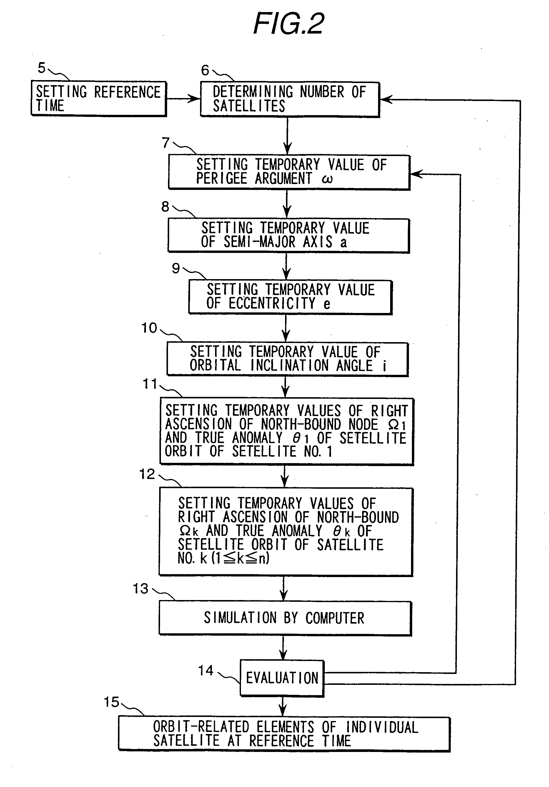
[0114] Method of setting the orbital elements (algorithm)

[0115] Examples of set values of the orbital elements and orbit configuration by the algorithm

[0116] Method of realizing and controlling the set orbital elements

[0117] Systems employing an artificial satellite traveling on the orbit according to the present invention

(1) Method of Setting the Orbital Elements (Algorithm)

[0118] Corresponding to each of the above items (a), (b) and (c), description will be made on the methods with regard to the items (a) and (b) below. With regard to the problem (c), setting of an argument of perigee is solved by the item (a) and a method of arranging a plurality of artificial satellites is solved by the item (b). Therefore, initially, numerical ranges of an orbital elements suitable for mobile broadcast and communication using the group of artificial satellites in Japan will be described here...


PUM


Abstract

A communication system having a plurality of artificial satellites each having a communication unit traveling on elliptical orbits with an orbital period of 24 hours. Arguments of perigee are set to values with a predetermined allowance in a setting process of the plurality of artificial satellites.

Description

CROSS REFERENCE TO RELATED APPLICATION [0001] This a continuation of U.S. application Ser. No. 10 / 410,174, filed Apr. 10, 2003, which is a continuation U.S. application Ser. No. 09 / 471,503, filed Dec. 23, 1999, now U.S. Pat. No. 6,695,259, which is a continuation-in-part of U.S. application Ser. No. 09 / 081,551, filed May 20, 1998, now U.S. Pat. No. 6,352,222, the subject matter of which is incorporated by reference herein. BACKGROUND OF THE INVENTION [0002] The present invention relates to a communication system, and a communication sending and receiving device and a communication terminal in the system, and particularly to a communication system suitable for a satellite, a satellite orbit and a satellite orbit configuration algorithm usable in the field of communication and broadcast such as satellite communication, satellite broadcast, satellite mobile communication and in the field of observation with regard to a celestial body of the satellite traveling around, and suitable for ...

Claims


Application Information

Patent Timeline
IPC IPC(8): B64G1/10B64G1/24H04B7/195
CPCB64G1/1007B64G1/1085H04B7/195H04B7/18558B64G1/242
Inventor MAEDA, TOSHIHIDEHAMANO, NOBUONAKAMURA, SHIGEKIYOSHIDA, TOMIHARUOWADA, MASATAKAIKEDA, MASAHIKOYABUTANI, TAKASHIITO, MASAHIRO
Owner MAEDA TOSHIHIDE
Learn More