Formation of a field reversed configuration for magnetic and electrostatic confinement of plasma

a plasma and field reverse configuration technology, applied in the field of plasma physics, can solve the problems of low efficiency (less than 30%), high radioactivity, and damage to the reactor walls, and achieve the effect of preventing anomalous electron transport and small gyroradius

Inactive Publication Date: 2005-08-18
RGT UNIV OF CALIFORNIA
View PDF49 Cites 1 Cited by
  • Summary
  • Abstract
  • Description
  • Claims
  • Application Information

AI Technical Summary

Benefits of technology

[0018] In a preferred embodiment, a plasma confinement system comprises a chamber, a magnetic field generator for applying a magnetic field in a direction substantially along a principle axis, and an annular plasma layer that comprises a circulating beam of ions. Ions of the annular plasma beam layer are substantially contained within the chamber magnetically in orbits and the electrons are substantially contained in an electrostatic energy well. In one aspect of one preferred embodiment a magnetic field generator comprises a current coil. Preferably, the system further comprises mirror coils near the ends of the chamber that increase the magnitude of the applied magnetic field at the ends of the chamber. The system may also comprise a beam injector for injecting a neutralized ion beam into the applied magnetic field, wherein the beam enters an orbit due to the force caused by the applied magnetic field. In another aspect of the preferred embodiments, the system forms a magnetic field having a topology of a field reversed configuration.
[0023] Magnetic confinement is ineffective for electrons because they have a small gyroradius—due to their small mass—and are therefore sensitive to short-wavelength fluctuations that cause anomalous transport. Therefore, the electrons are effectively confined in a deep potential well by an electrostatic field, which tends to prevent the anomalous transport of energy by electrons. The electrons that escape confinement must travel from the high density region near the null surface to the surface of the plasma. In so doing, most of their energy is spent in ascending the energy well. When electrons reach the plasma surface and leave with fusion product ions, they have little energy left to transport. The strong electrostatic field also tends to make all the ion drift orbits rotate in the diamagnetic direction, so that they are contained. The electrostatic field further provides a cooling mechanism for electrons, which reduces their radiation losses.
[0025] Another advantage of the advanced fuels is the direct energy conversion of energy from the fusion reaction because the fusion products are moving charged particles, which create an electrical current. This is a significant improvement over Tokamaks, for example, where a thermal conversion process is used to convert the kinetic energy of fast neutrons into electricity. The efficiency of a thermal conversion process is lower than 30%, whereas the efficiency of direct energy conversion can be as high as 90%.

Problems solved by technology

The disadvantages of neutronic reactions are that (1) the flux of fast neutrons creates many problems, including structural damage of the reactor walls and high levels of radioactivity for most construction materials; and (2) the energy of fast neutrons is collected by converting their thermal energy to electric energy, which is very inefficient (less than 30%).
The advanced fuels have disadvantages, too.
Also, it is much more difficult to cause the advanced fuels to fuse.
Electrons, however, have a much smaller gyroradius, so they respond to the fluctuations and transport anomalously.
A Tokamak reactor using D-T fuel has the additional problem that most of the energy of the fusion products energy is carried by 14 MeV neutrons, which cause radiation damage and induce reactivity in almost all construction materials due to the neutron flux.
In addition, the conversion of their energy into electricity must be by a thermal process, which is not more than 30% efficient.
Producing useful fusion reactions in this type of reactor has been infeasible because the background plasma slows down the ion beams.
In none of these devices, however, does an equilibrium electric field play any part.
None of these patents consider electrostatic confinement of electrons and magnetic confinement of ions.
Although there have been many research projects on electrostatic confinement of ions, none of them have succeeded in establishing the required electrostatic fields when the ions have the required density for a fusion reactor.
Lastly, none of the patents cited above discuss a field reversed configuration magnetic topology.

Method used


Image

  • Formation of a field reversed configuration for magnetic and electrostatic confinement of plasma
  • Formation of a field reversed configuration for magnetic and electrostatic confinement of plasma
  • Formation of a field reversed configuration for magnetic and electrostatic confinement of plasma

Examples


experiment 1

[0185] Propagating and Trapping of a Neutralized Beam in a Magnetic Containment Vessel to Create an FRC.

[0186] Beam propagation and trapping were successfully demonstrated at the following parameter levels: [0187] Vacuum chamber dimensions: about 1 m diameter, 1.5 m length. [0188] Betatron coil radius of 10 cm. [0189] Plasma beam orbit radius of 20 cm. [0190] Mean kinetic energy of streaming beam plasma was measured to be about 100 eV, with a density of about 1013 cm−3, kinetic temperature on the order of 10 eV and a pulse-length of about 20 μs. [0191] Mean magnetic field produced in the trapping volume was around 100 Gauss, with a ramp-up period of 150 μs. Source: Outer coils and betatron coils. [0192] Neutralizing background plasma (substantially Hydrogen gas) was characterized by a mean density of about 1013 cm3, kinetic temperature of less than 10 eV.

[0193] The beam was generated in a deflagration type plasma gun. The plasma beam source was neutral Hydrogen gas, which was inje...

experiment 2

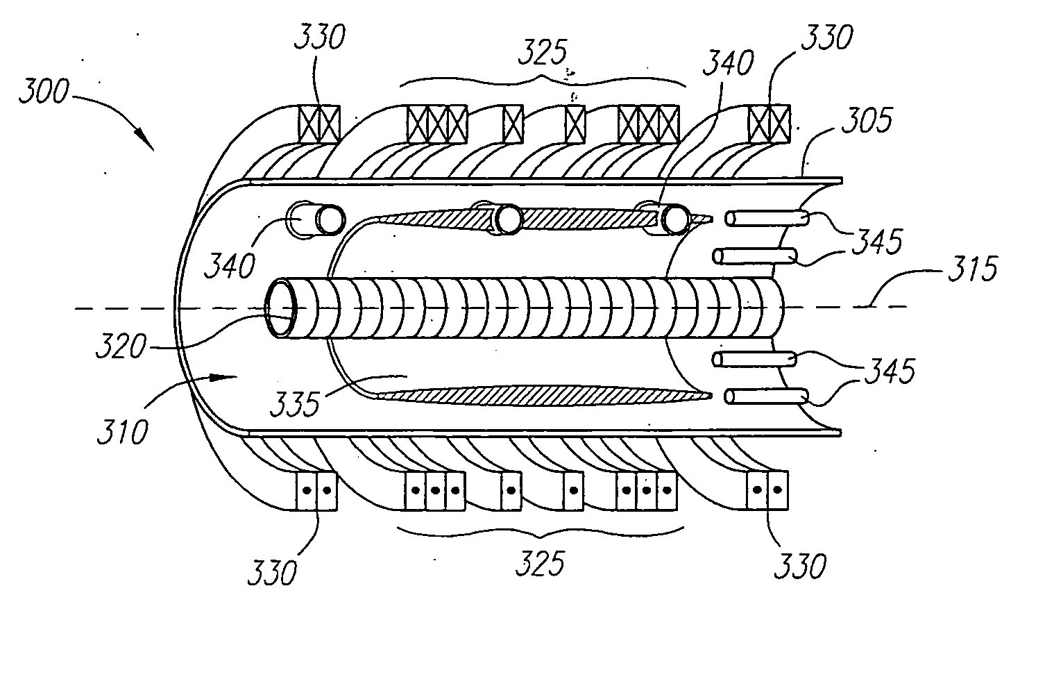
[0197] FRC Formation Utilizing the Combined Beam / Betatron Formation Technique.

[0198] FRC formation was successfully demonstrated utilizing the combined beam / betatron formation technique. The combined beam / betatron formation technique was performed experimentally in a chamber 1 m in diameter and 1.5 m in length using an externally applied magnetic field of up to 500 G, a magnetic field from the betatron flux coil 320 of up to 5 kG, and a vacuum of 1.2×10⁻⁵ torr. In the experiment, the background plasma had a density of 1013 cm−3 and the ion beam was a neutralized Hydrogen beam having a density of 1.2×1013 cm3, a velocity of 2×107 cm / s, and a pulse length of around 20 Us (at half height). Field reversal was observed.

experiment 3

[0199] FRC Formation Utilizing the Betatron Formation Technique.

[0200] FRC formation utilizing the betatron formation technique was successfully demonstrated at the following parameter levels: [0201] Vacuum chamber dimensions: about 1 m diameter, 1.5 m length. [0202] Betatron coil radius of 10 cm. [0203] Plasma orbit radius of 20 cm. [0204] Mean external magnetic field produced in the vacuum chamber was up to 100 Gauss, with a ramp-up period of 150 μs and a mirror ratio of 2 to 1. (Source: Outer coils and betatron coils). [0205] The background plasma (substantially Hydrogen gas) was characterized by a mean density of about 1013 cm3, kinetic temperature of less than 10 eV. [0206] The lifetime of the configuration was limited by the total energy stored in the experiment and generally was around 30 μs.

[0207] The experiments proceeded by first injecting a background plasma layer by two sets of coaxial cable guns mounted in a circular fashion inside the chamber. Each collection of 8 gu...


PUM


Abstract

A system and method for containing plasma and forming a Field Reversed Configuration (FRC) magnetic topology are described in which plasma ions are contained magnetically in stable, non-adiabatic orbits in the FRC. Further, the electrons are contained electrostatically in a deep energy well, created by tuning an externally applied magnetic field. The simultaneous electrostatic confinement of electrons and magnetic confinement of ions avoids anomalous transport and facilitates classical containment of both electrons and ions. In this configuration, ions and electrons may have adequate density and temperature so that upon collisions they are fused together by nuclear force, thus releasing fusion energy. Moreover, the fusion fuel plasmas that can be used with the present confinement system and method are not limited to neutronic fuels only, but also advantageously include advanced fuels.

Description

CROSS-REFERENCE TO RELATED APPLICATIONS [0001] This application is a continuation of U.S. Ser. No. 10 / 328,701 filed Dec. 23, 2002, which is a continuation of U.S. Ser. No. 10 / 066,424, filed Jan. 31, 2002, which applications are fully incorporated herein by reference, and which is related to provisional U.S. application Ser. No. 60 / 266,074, filed Feb. 1, 2001, and provisional U.S. application Ser. No. 60 / 297,086, filed on Jun. 8, 2001, which applications are fully incorporated herein by reference.[0002] This invention was made with Government support under Contract No. N00014-99-1-0857, awarded by the Office of Naval Research. Some background research was supported by the U.S. Department of Energy for 1992 to 1993. The Government has certain rights in this invention.FIELD OF THE INVENTION [0003] The invention relates generally to the field of plasma physics, and, in particular, to methods and apparati for confining plasma. Plasma confinement is particularly of interest for the purpos...

Claims


Application Information

Patent Timeline
Patent Type & Authority Applications(United States)
IPC IPC(8): G21B1/00G21B1/05G21B1/11G21D7/00H05H1/12H05H1/16
CPCG21B1/052G21D7/00H05H1/16Y02E30/122H05H1/03H05H1/14G21B1/05H05H1/12Y02E30/10Y02E30/00H05H1/02H05H1/10
Inventor ROSTOKER, NORMANBINDERBAUER, MICHLQERUSHI, ARTANTAHSIRI, HOOSHANG
Owner RGT UNIV OF CALIFORNIA
Why Eureka
Try Eureka