Method of manufacturing liquid container, and liquid container

Inactive Publication Date: 2005-08-18
SEIKO EPSON CORP
View PDF9 Cites 19 Cited by
  • Summary
  • Abstract
  • Description
  • Claims
  • Application Information

AI Technical Summary

Benefits of technology

[0019] According to the invention, since blocking of the bypass flowing passage is performed by heat welding, for example, compared with blocking by vibration welding, it is possible to prevent foreign material from entering into the liquid container, and also time necessary for blocking can

Problems solved by technology

However, since in the ink pack disclosed in the Patent Reference 1, the valve unit provided for the outlet part functions as the check valve, the ink cannot be poured through the outlet part.
Further, when the ink pack fi

Method used


Image

  • Method of manufacturing liquid container, and liquid container
  • Method of manufacturing liquid container, and liquid container
  • Method of manufacturing liquid container, and liquid container

Examples


first embodiment

[0032] First Embodiment

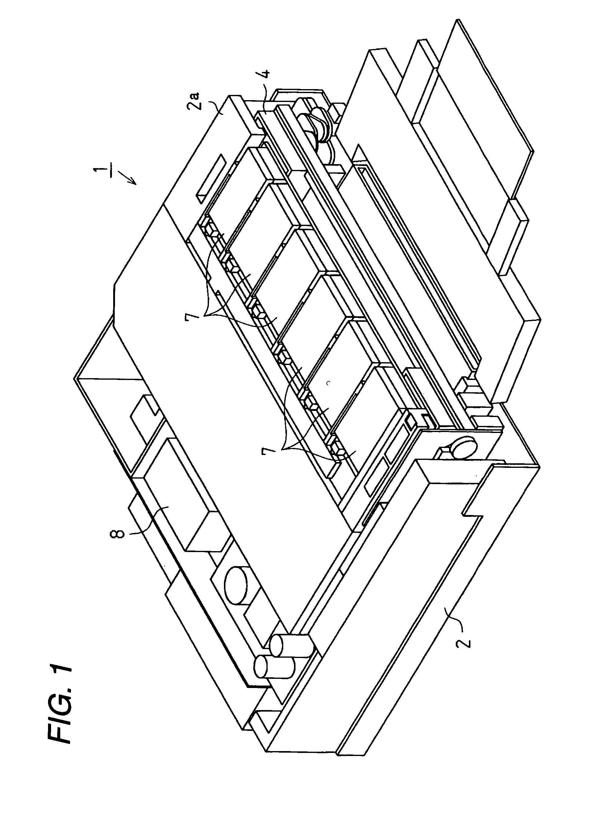
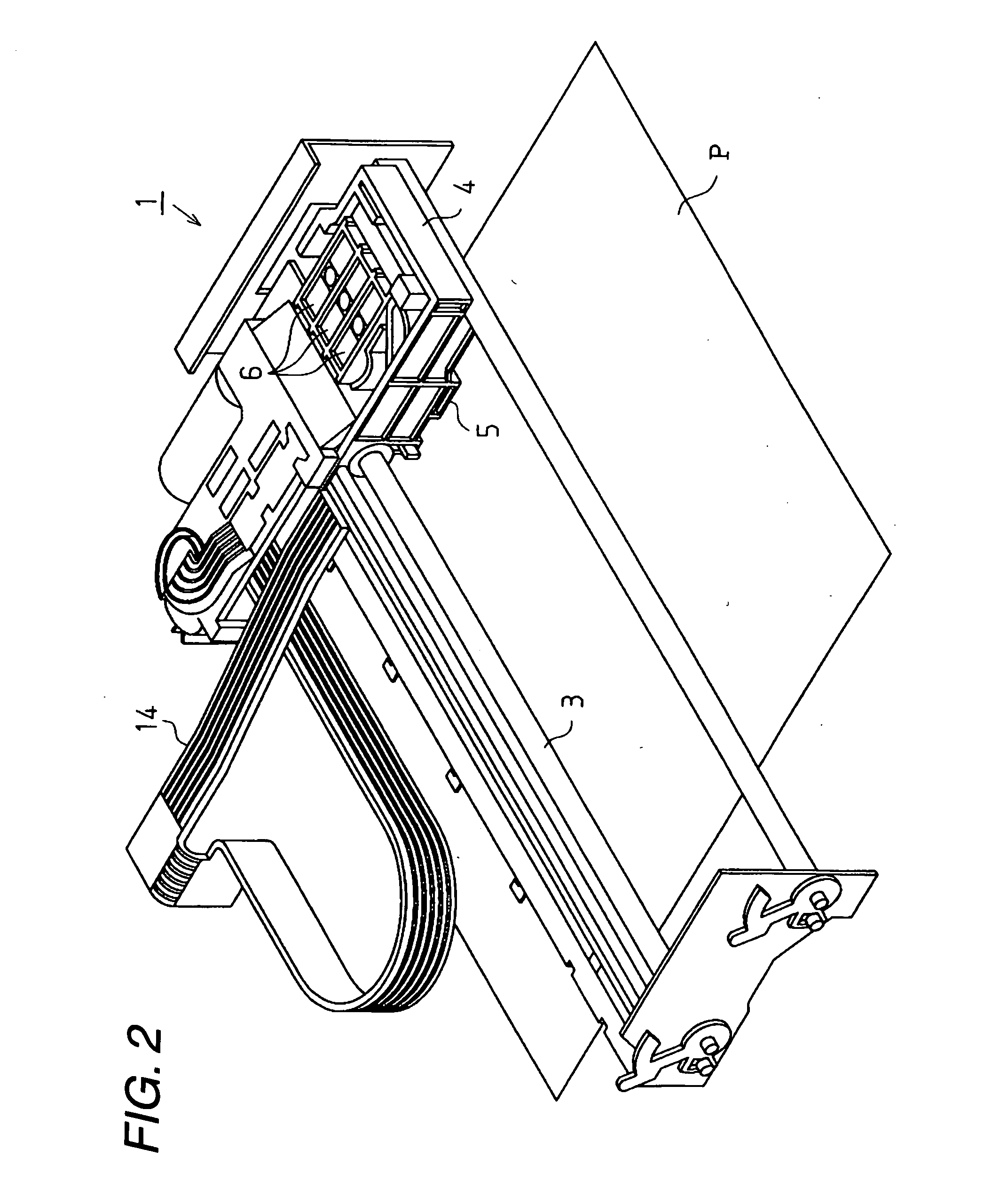
[0033] A first embodiment of the invention will be described below with reference to FIGS. 1 to 6. FIG. 1 is a perspective view of an ink jet type recording apparatus (hereinafter referred to simply as a printer 1) used as a liquid jet apparatus in the embodiment, FIG. 2 is a main portion perspective view of the printer 1, and FIG. 3 is an exploded perspective view of an ink cartridge provided for the printer 1.

[0034] As shown in FIG. 1, the printer 1 in the embodiment is an ink jet type, and includes a frame 2. Inside the frame 2, as shown in FIG. 2, a guide member 3, a carriage 4, a recording head 5, and a valve unit 6 are provided. Further, the printer 1 is provided, as shown in FIG. 1, with an ink cartridge 7 as a liquid container, and an air pressure pump 8. The frame 2 is a box body formed generally in the shape of a rectangular parallelepiped, and has a cartridge holder 2a on its front surface.

[0035] The guide member 3, as shown in FIG. 2, is formed i...

second embodiment

[0079] Second Embodiment

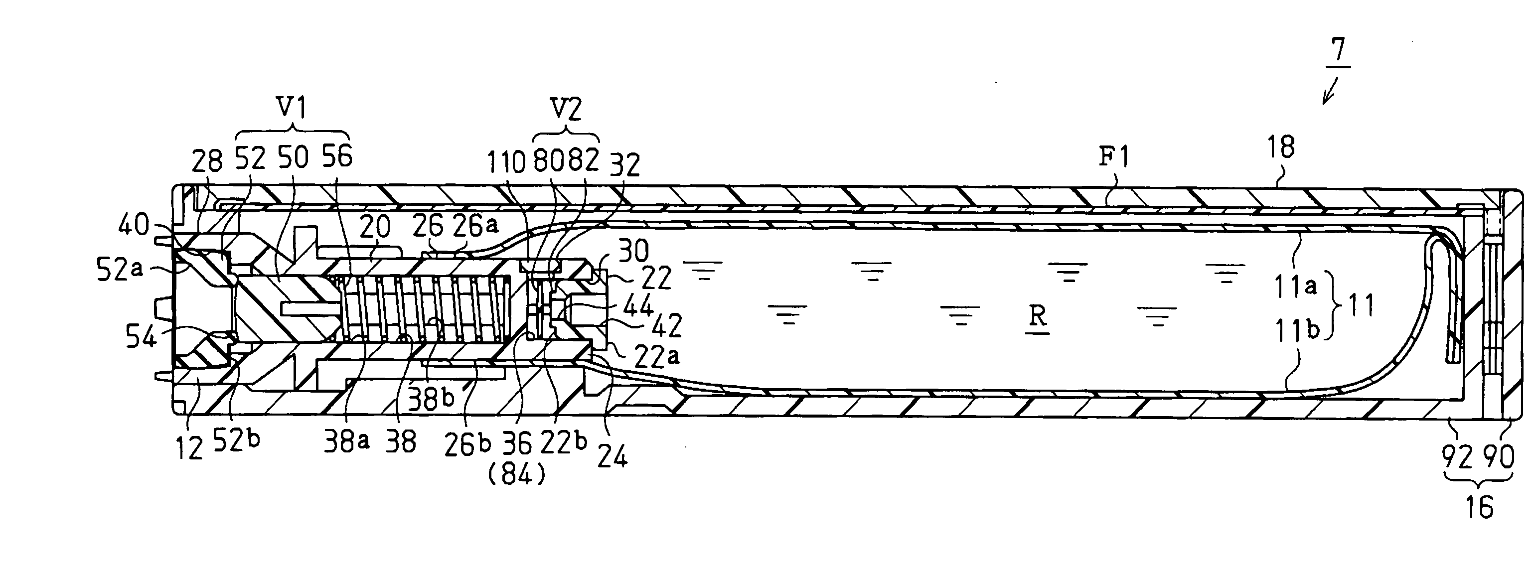
[0080] Next, a second embodiment of the invention will be described with reference to FIGS. 7 and 8. This embodiment is characterized by a blocking method of the bypass flowing passage 32 of the ink pack 10 described in the first embodiment. In the following description, the same parts as those in the first embodiment are denoted by the same reference characters, and their detailed descriptions are omitted.

[0081] As shown in FIG. 7, in the ink pack 10 before the ink is filled, a blocking means, that is, a blocking member 110 as a stopper is coupled to the outlet part 12 rotatably in relation to the opening part of the bypass flowing passage 32. The blocking member 110 is coupled through a coupling part 110a to the outlet part 12, and rotates about the coupling part 110a. The blocking member 110 is usually arranged in a position where the bypass flowing passage 32 is opened. When the blocking member 110 is pressed from the upside, it rotates about the couplin...


PUM


Abstract

Since a bypass flowing passage 32 which communicates with the inside of a bag part 11 not through a second valve mechanism V2 is provided for an outlet part 12, ink can be filled from the outlet part 12 into the bag part 11 in spite of the existence of the second valve mechanism V2. Further, after an ink pack that has been yet filled with ink has been housed in an inner case 92, the ink is filled into the ink pack. Therefore, when a first seal film F1 is welded to the inner case 92, since the bag part 11 is not bulky, the ends of the bag part 11 are caught in a cartridge case. Therefore, the maximum amount of ink for the inner volume of the cartridge case can be filled. Further, since a bypass flowing passage 32 is blocked after the ink has filled into the ink pack, contamination of air bubbles into the bag part 11 through the bypass flowing passage 32 is prevented.

Description

BACKGROUND OF THE INVENTION [0001] The present invention relates to a method of manufacturing a liquid container, and a liquid container. [0002] As a liquid jet apparatus which jets liquid to a target, an ink jet type recording apparatus has been known widely. Specifically, this ink jet type recording apparatus includes a carriage, a recording head mounted on the carriage, and an ink cartridge which contains ink as liquid therein. While the carriage is being moved in relation to a recording medium, the ink is supplied from the ink cartridge to the recording head, and the ink is ejected from a nozzle formed in the recording head, whereby printing is performed on the recording medium. [0003] In such the ink jet type recording apparatuses, there is an apparatus in which an ink cartridge is not mounted on a carriage in order to reduce load onto the carriage or to reduce size / thickness of the apparatus (so-called Off-carriage type). [0004] Such the ink cartridge includes usually an ink p...

Claims


Application Information

Patent Timeline
IPC IPC(8): B05C11/10B41J2/175B41J2/195
CPCB41J2/17559
Inventor SEINO, TAKEOKIMURA, HITOTOSHIISHIZAWA, TAKUUEHARA, YASUNAOMATSUYAMA, MASAHIDE
Owner SEIKO EPSON CORP
Why Eureka
Try Eureka