Print media edge printing

a printing media and edge technology, applied in the field of printing, can solve the problems of ink collection arrangement occupying a considerable amount of space and printing is not continuous, and achieve the effect of improving the visual appearan

Inactive Publication Date: 2005-08-18
HEWLETT PACKARD DEV CO LP
View PDF6 Cites 116 Cited by
  • Summary
  • Abstract
  • Description
  • Claims
  • Application Information

AI Technical Summary

Benefits of technology

[0020] A single printhead may be provided for a single colour, e.g. black. Alternatively, the apparatus may comprise a plurality of printheads corresponding to different coloured inks. An additional printhead may be provided for applying fixer to the print media. A fixer is a liquid applied to a print media to restrict the spreading of another liquid (usually ink) through the

Problems solved by technology

When, however, the sheet is to be printed with a relatively small bottom margin, or no margin at all, the sheet is released from the pinch between the feed roller and the pinch wheel before printing is finished and this causes

Method used


Image

  • Print media edge printing
  • Print media edge printing
  • Print media edge printing

Examples


first embodiment

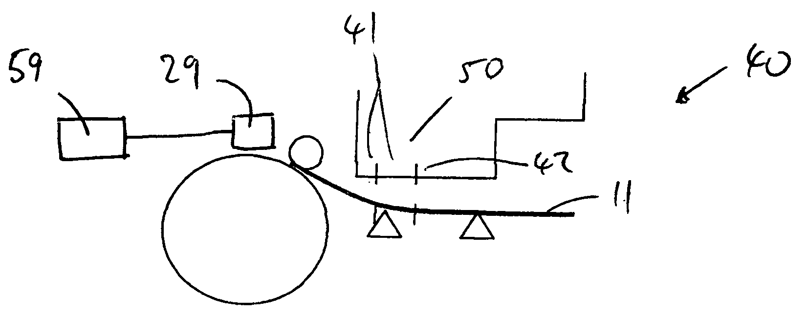
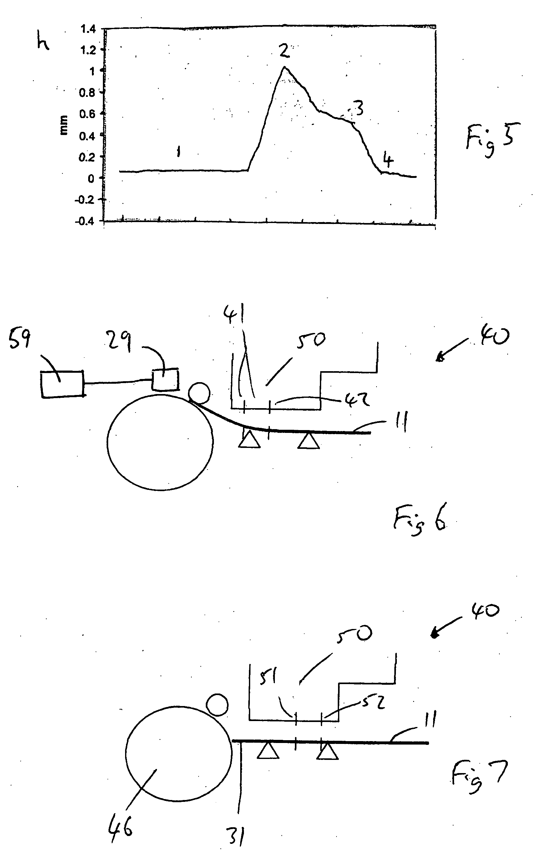
[0041] Referring now to FIGS. 6 and 7, the present invention comprises a printing mechanism 40 similar to that shown in FIGS. 1 to 4. However, it will be seen from FIG. 6 that only the nozzles in the group located between lines 41 and 42 in the left-hand side of the printhead 50 are used to fire ink onto the main central region of the print media 11. In FIG. 6, the paper media 11 is just about to be released from the pinch.

[0042] The printing process is under the control of a printing controller 59. As printing proceeds down the print media, the position of the trailing edge 31 of print media 11 is monitored by a paper sensor 29 directly (e.g. optically) and / or indirectly (e.g. by summing the preceding print media advance movements). Sensor 29 is connected to controller 59. In the present embodiment, instead of continuing uniform medium advances through the positions indicated in FIGS. 2 and 3, the print media is caused to undertake a relatively long advance movement to the position...

second embodiment

[0057] the present invention, which seeks to remove or at least further reduce the remaining printing artefacts, will now be described in connection with FIGS. 10 to 13.

[0058] Typically a scanning printhead comprises 304 nozzles arranged in two lines, of which 288 nozzles are used to fire ink on to a print media. To avoid print defects, it is usually the nozzles at the ends of the lines which are not used. In the second embodiment, the main region of the print media is printed in four passes with swaths having effectively full swath height, i.e. 288 nozzles. This will be called Print Mode A. As the bottom edge region is approached the number of nozzles used to fire ink is progressively reduced. This involves two stages: firstly the modification of the printing mask so that a reduced number of nozzles is used, and secondly the print media advance is reduced. Printing in the second stage will be called Print mode B.

[0059]FIG. 10 shows the printing mask 70 used in the first stage, whi...

third embodiment

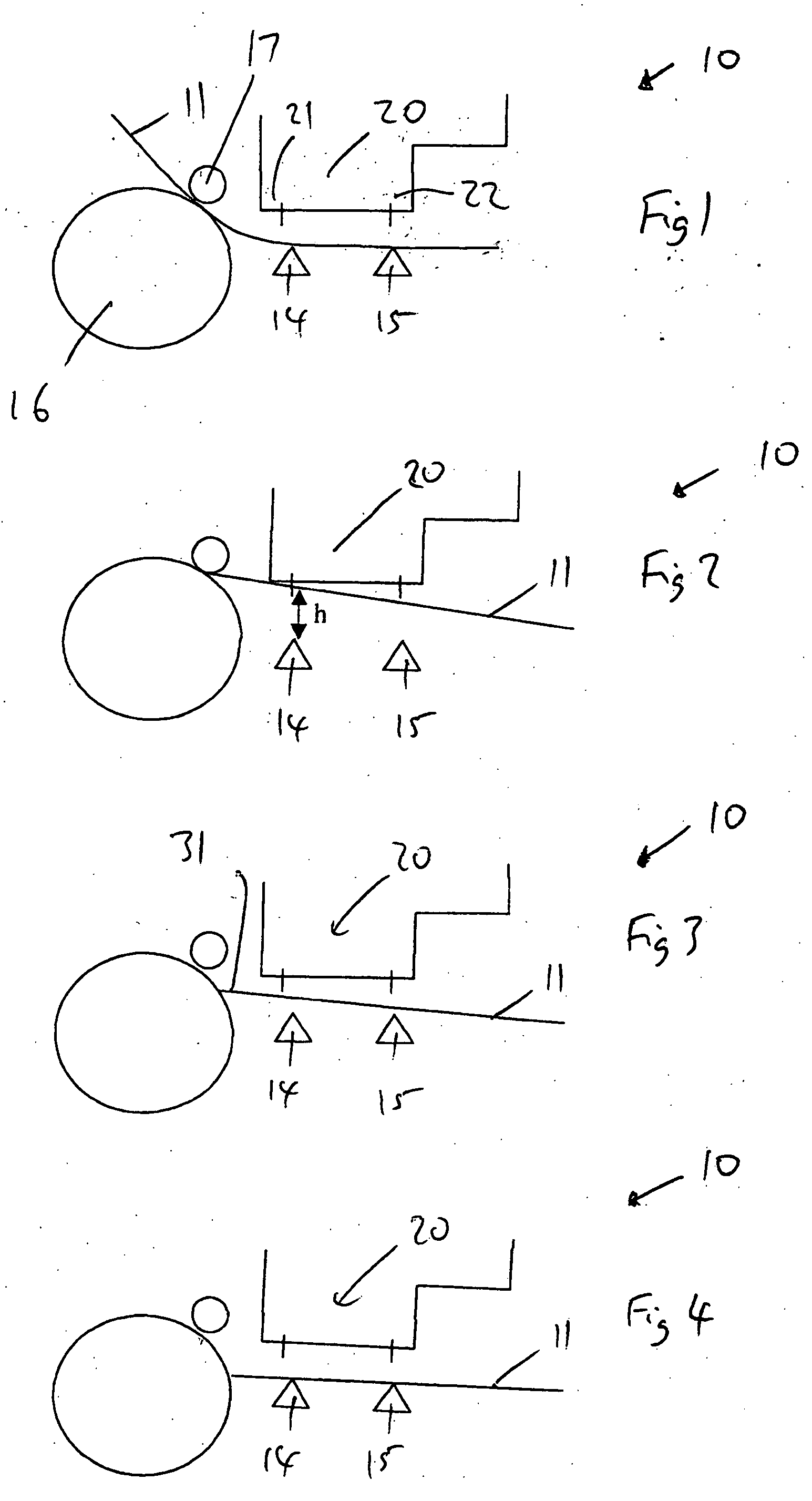
[0070] Before turning to the present invention, reference will first be made to a prior art printing mechanism 110 shown in FIG. 14. The mechanism comprises a feeder roller 116 and an associated pinch wheel 117 which feed a sheet of print media 11 towards a print zone on a platen comprising ribs 114, 214, 314 extending across the width of the platen in a direction perpendicular to that of print media advance beneath a printhead 120. In the channels formed between the ribs 114, 214 and 214, 314 there are provided strips of ink-absorbent material 115, 215 which serve to absorb ink fired during a full bleeding printing operation as described in the introduction. Substantially the whole length of printhead 120 is employed, indicated by region 216, so that it is necessary to provide absorbent material beneath the whole of region 216. In the mechanism of FIG. 12, this means that the end ribs 114, 314 need to be located substantially outside the region 216. This leads to there being a sepa...


PUM


Abstract

In printing apparatus, when printing near the end of a print media with a printhead having nozzles, a controller causes a print drive to produce a large print media advance movement together with the use of a different group of nozzles from that used for the rest of the print media. This avoids printing artefacts as the print media leaves a pinch in a media feed. In one embodiment the number of nozzles used for printing in the end region is reduced, and the center of the group of nozzles is simultaneously shifted in the direction of print media advance. The size of the print media advance is also changed in the end region. The printing mask used is also changed.

Description

BACKGROUND TO THE INVENTION [0001] The present invention relates to printing at or near the edges or ends of print media by hardcopy devices. In particular it relates to so-called bleed printing or zero margin printing in which printheads of a hardcopy device apply ink to a print media right up to, and in some cases beyond, its edges. [0002] When printing a sheet of print media in a hardcopy device, it is fed on to a platen in the print zone in a controlled manner by passing it between a feed roller and a pinch wheel. When the page or sheet has an unprinted bottom margin of conventional size, good print quality can be maintained throughout the sheet, since the trailing edge of the sheet remains held between the feed roller and the pinch wheel until printing of the sheet has finished. When, however, the sheet is to be printed with a relatively small bottom margin, or no margin at all, the sheet is released from the pinch between the feed roller and the pinch wheel before printing is ...

Claims


Application Information

Patent Timeline
IPC IPC(8): B41J2/01B41J11/00
CPCB41J11/0095B41J11/0065
Inventor CAMPILLO, ALEJANDROVECIANA, JOAQUIMRUFES, EZEQUIEL JORDICERCOS, ANGELSERRA, MARCGONZALEZ, DANIELHINOJOSA, ANTONIORODRIGUEZ, SERVANDO
Owner HEWLETT PACKARD DEV CO LP
Why Eureka
Try Eureka