Light-guiding plate, lighting device and display device

a technology of light guiding plate and light guiding plate, which is applied in the direction of waveguides, lighting and heating apparatuses, instruments, etc., can solve the problems of uneven brightness, falling luminance near the light source, and dark lines at the emission surface, so as to reduce light and uniform luminance distribution

Inactive Publication Date: 2005-08-18
FUJITSU LTD
View PDF10 Cites 17 Cited by
  • Summary
  • Abstract
  • Description
  • Claims
  • Application Information

AI Technical Summary

Benefits of technology

[0034] Due to the above characteristics, the effects are exhibited that it is possible to reduce the light near the light source in a planar lighting device and that a planar lighting device having an overall uniform luminance distribution including near the light source can be realized.

Problems solved by technology

Further, the weak intensity light sometimes becomes a cause of dark lines at the emission surface.
In a side light type backlight, there is the problem of the occurrence of uneven brightness including bright lines and dark lines.
Further, in a conventional side light type backlight, the entering surface is not processed at all, so there is the problem of the luminance near the light source ending up falling. FIG. 30 shows the results of verification of the luminance distribution in a perpendicular direction from the light source due to differences in treatment of entering surfaces.
Further, part of the light scattered at the incident surface of the light-guiding plate is not effectively propagated inside the light-guiding plate and the efficiency of utilization of the light drops.
By diffusion treatment of the entering surface, the luminance near the light source rises, but the amount of light at the far part becomes smaller, so there was the problem that the luminance ended up gradually falling.
However, if highly oriented light strikes the incident surface of the light-guiding plate, the amount of emission of light from the end part of the light-guiding plate near the light source becomes smaller and the uneven luminance at the end part of the light-guiding plate near the light source is not eliminated.
However, this prior art can only be used in a basic configuration where the end part of the reflection sheet is arranged between the light-guiding plate and one end part of the reflector, and the other end part of the reflector is in close contact with the light-guiding plate.
When the end part of the reflection sheet is arranged at the outside from one end part of the reflector or when there is a gap between the other end part of the reflector and the light-guiding plate, this prior art cannot be applied.

Method used


Image

  • Light-guiding plate, lighting device and display device
  • Light-guiding plate, lighting device and display device
  • Light-guiding plate, lighting device and display device

Examples


Embodiment Construction

[0083] The embodiments of the present invention will be now explained with reference to the drawings.

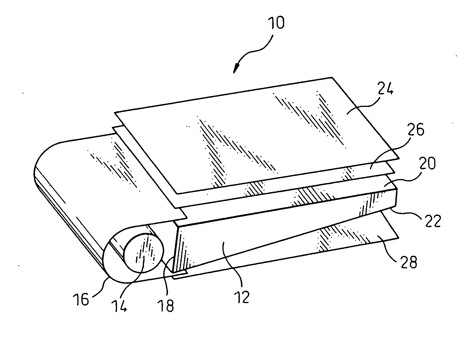
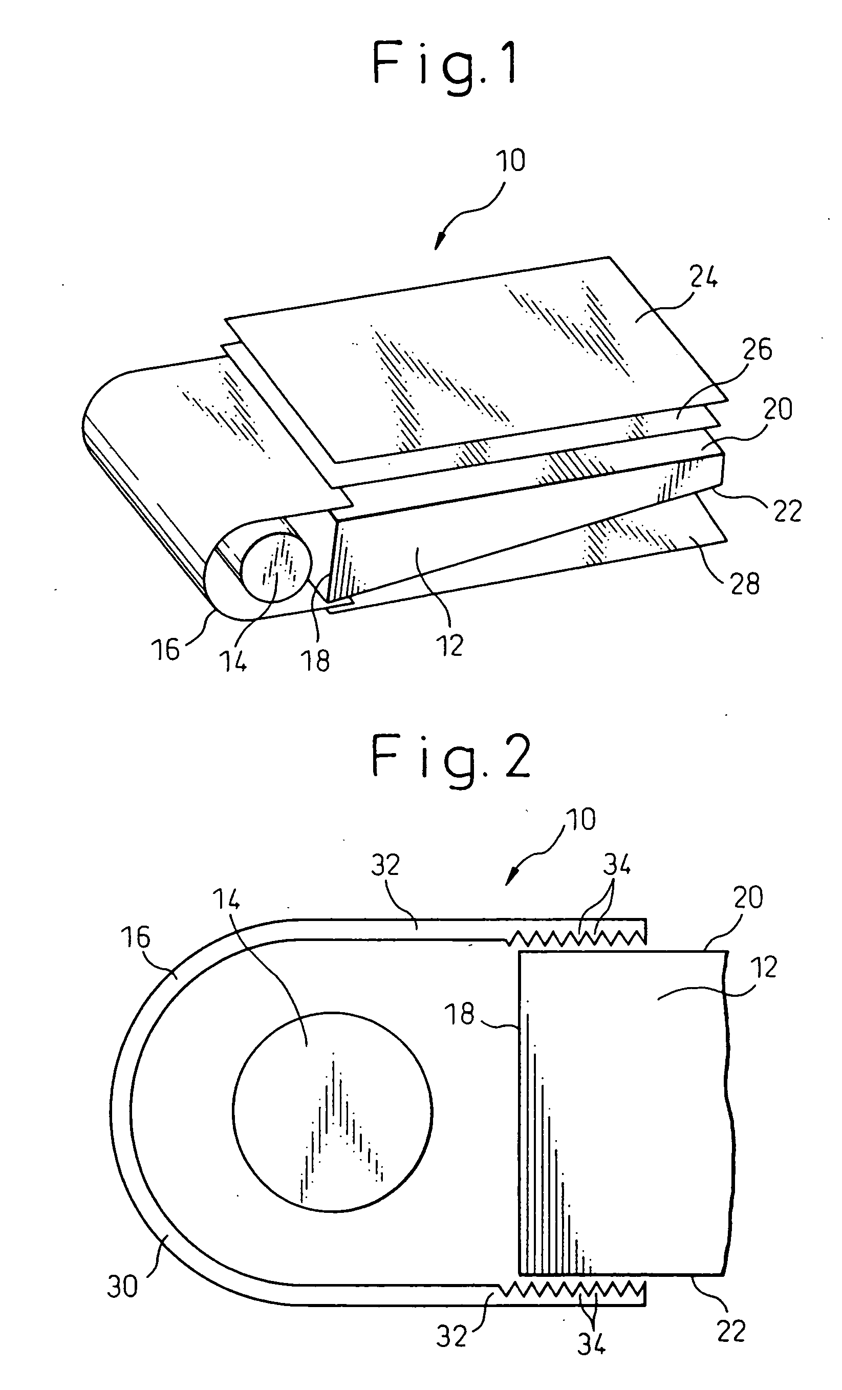
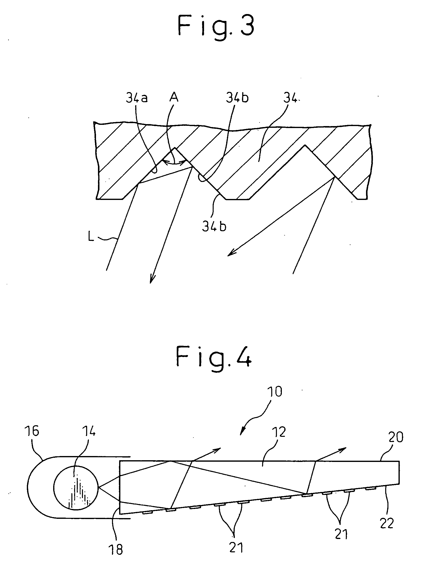
[0084]FIG. 1 is a schematic perspective view of a lighting device 10 of an embodiment of the present invention. FIG. 2 is an enlarged side view of part of the lighting device of FIG. 1. FIG. 3 is a sectional view of projections or depressions 34 at an inside surface of an end part 32 of a reflector 16 of FIG. 2.

[0085] The lighting device 10 is comprised of a light-guiding plate 12, a rod-shaped light source 14 comprised of a cold cathode fluorescent lamp arranged on one side of the light-guiding plate 12, and a reflector 16 covering the light source 14.

[0086] The light-guiding plate 12 has an incident surface (end surface) 18 extending long parallel to the light source 14, an emission surface (top surface) 20 substantially perpendicular to the incident surface 18, and a reflection surface (bottom surface) 22 at the side opposite to the emission surface 20. The light-guiding plate ...


PUM

PropertyMeasurementUnit
refractive indexaaaaaaaaaa
angleaaaaaaaaaa

Abstract

A reflector has a curved part covering the light source and a pair of end parts extending at the two sides of the curved part. The inside surface of each end part has a plurality of substantially parallel projections or depressions. The light-guiding plate has an incident surface and an emission surface substantially perpendicular to the incident surface, the incident surface having a plurality of projections or depressions extending substantially parallel to the emission surface. Also, the reflection surface of the light-guiding plate has projections.

Description

BACKGROUND OF THE INVENTION [0001] 1. Field of the Invention [0002] The present invention relates to a reflector, a light, a light-guiding plate, and a display. [0003] 2. Description of the Related Art [0004] In a display of a PC, a liquid crystal television, etc., a side light type light is used. In the case of a transmission type liquid crystal display device, a planar lighting device (backlight) is arranged on the back surface side of the liquid crystal panel. A side light type backlight includes a light-guiding plate, a light source arranged on one side of the light-guiding plate, and a reflector. [0005] A reflector has for example a semicircular sectional shape or U-shape and is arranged to cover the light source, extend to the end parts of the light-guiding plate, and partially overlap the light-guiding plate. The light striking the incident surface of the light-guiding plate proceeds inside the light-guiding plate while being reflected. Therefore, to make the light be emitted...

Claims


Application Information

Patent Timeline
Patent Type & Authority Applications(United States)
IPC IPC(8): G02B6/00F21V8/00F21Y103/00G02F1/1335G02F1/13357
CPCG02B6/0016G02B6/002G02B6/0031Y10S385/901G02B6/0038G02B6/0043G02B6/0053G02B6/0036G02F1/1335
Inventor HARA, YASUSHINISHIO, CHIKARAABE, MAKOTOHIRABAYASHI, MASASHIYAMADA, HIROSHITAKAHASHI, TOSHIKAZUTANAKA, AKIRA
Owner FUJITSU LTD
Why Eureka
Try Eureka