
Platform gate door device

a platform gate and gate technology, applied in railway stations, instruments, roads, etc., can solve the problems of not completely preventing the entry of disturbance lights at certain incident angles, the detection device cannot detect the presence of obstacles, and it is difficult to determine which obstacle detectors showed the true detection, etc., to achieve the effect of determining the occurrence of failur

Active Publication Date: 2005-08-25
HIATACHI POWER SOLUTIONS CO LTD
View PDF3 Cites 10 Cited by
  • Summary
  • Abstract
  • Description
  • Claims
  • Application Information

AI Technical Summary

Benefits of technology

[0009] The object of the present invention is to provide a platform gate door device equipped with a highly reliable photoelectric obstacle detector that does not malfunction by disturbance light that moves, such as sunlight.
[0010] Another object of the present invention is to provide a platform gate door device equipped with the above photoelectric obstacle detector, capable of easily determining the failure of the photoelectric obstacle detector.
[0016] According to the present invention, it is possible to prevent without fail the disturbance light such as sunlight from being incident on the detector, and to effectively determine the occurrence of failure of the obstacle detector by installing a plurality of detectors.

Problems solved by technology

However, when ambient light (disturbance light) such as sunlight enters the light receiver, it may be possible that the detector cannot detect the presence of an obstacle.
According to this prior art example, only the amount of disturbance light such as sunlight is restricted or the incident angle of the disturbance light is limited, and it does not completely prevent the entry of disturbance light taking certain incident angles.
Furthermore, when two sets of obstacle detectors having the light emitter and the light receiver in inversed positions are disposed on each side of the door to detect the presence of an obstacle, if the results of detection of the two sets differ, it is difficult to determine which obstacle detector showed the true detection result.
Moreover, there was a drawback according to the prior art method using the filter in that when strong sunlight was incident on the light receiver, the modulated infrared radiation could not be detected by the receiver, according to which the detector may erroneously determine that an obstacle is present.

Method used


Image

  • Platform gate door device
  • Platform gate door device
  • Platform gate door device

Examples


second embodiment

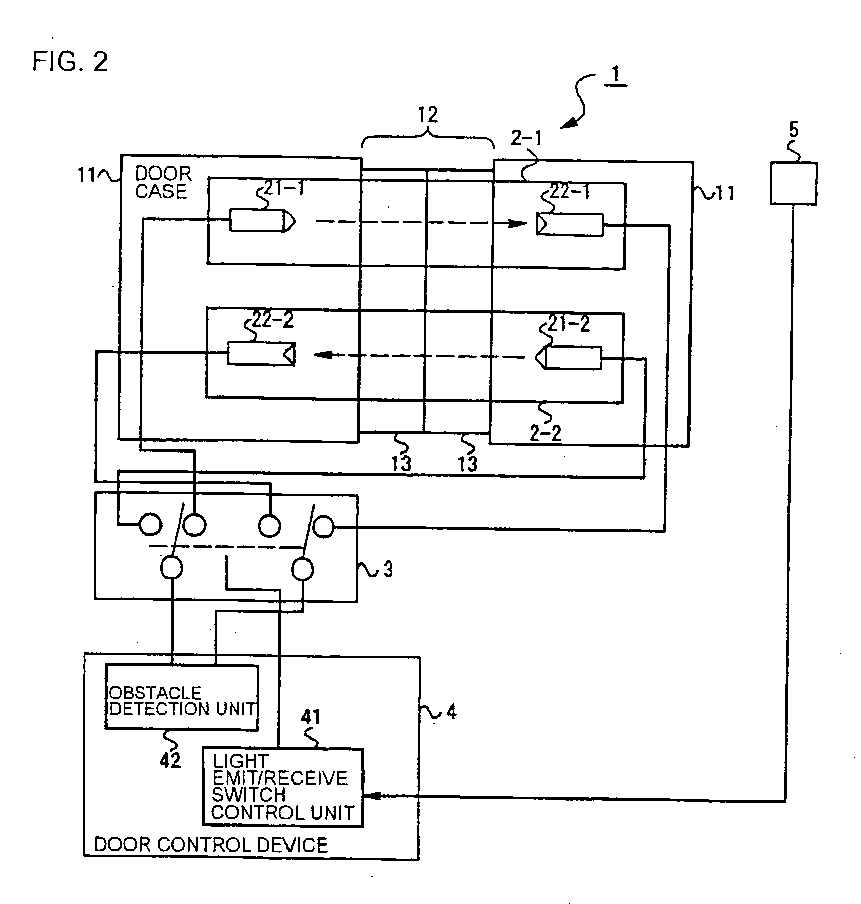
[0028]FIG. 2 is used to describe the structure of a platform gate door device according to the present invention. This embodiment carries out the light emit / receive switch control based on the strength of the received disturbance light, and for example, it has a disturbance light receiver 5 for receiving the disturbance light. When the amount of disturbance light received by the disturbance light receiver 5 exceeds a predetermined value, the light emit / receive switch control unit 41 switches the activation of the first obstacle detector 2-1 and the second obstacle detector 2-2. The set value for the amount of disturbance light should be determined so that the switching operation is carried out before the received light exceeds the range of normal operation of the light receiver 22.

[0029] According to the above arrangement, the platform gate door device can be operated without being affected by the disturbance light.

third embodiment

[0030]FIG. 3 is referred to in describing a platform gate door device according to the present invention. According to this embodiment, the platform gate door devices 1-1 through 1-n installed on a platform are subjected collectively to light emit / receive switch control. Each of the platform gate door devices 1-1 through 1-n receive switch information provided from a total control device 6 provided on each of the platforms or to cover a number of platforms, according to which the door control devices 4-1 through 4-n on each of the platform gate door devices 1 carry out switching control between the first and second obstacle detectors 2-1 and 2-2. The total control device 6 includes a clock, so there is no need to install clocks or disturbance light receiver 5 to each of the door control devices 4-1 through 4-n of the platform gate door devices 1-1 through 1-n. Further, the disturbance light receiver 5 can be installed on a light receiving end of the platform, and the signal output f...


PUM


Abstract

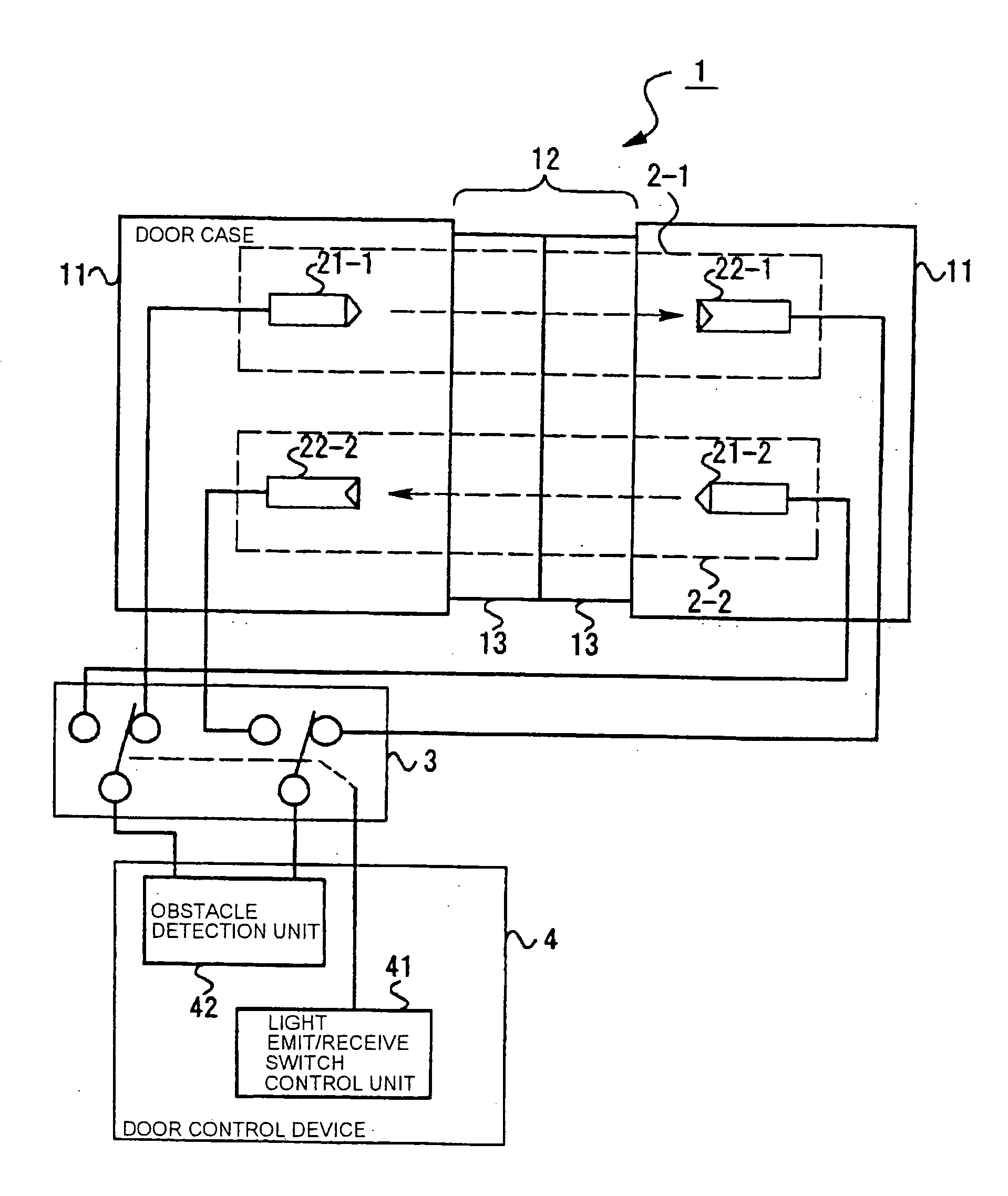
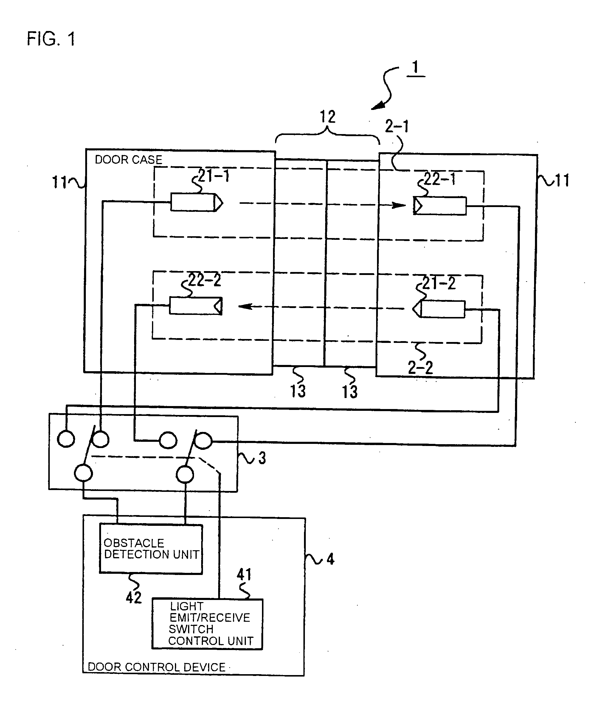
The invention provides a platform gate door device equipped with highly reliable photoelectric obstacle detectors that do not malfunction by disturbance light that moves, such as sunlight. The platform gate door device comprises a platform gate door 13 installed on a platform at a position where passengers get on and off a vehicle; a door control device 4 for opening and closing the platform gate door; at least two photoelectric obstacle detectors 2 disposed between the platform gate door 13 and the vehicle for detecting a presence of an obstacle, wherein each obstacle detector 2 has a light emitter 21 and a light receiver 22 disposed on either side of an opening 12 of the platform gate door, and wherein the obstacle detectors 2 are arranged so that the direction of emission from the light emitters are mutually inversed; and a switching means 3 for activating one of the plurality of obstacle detectors.

Description

[0001] The present application is based on and claims priority of Japanese patent application No. 2004-041010 filed on Feb. 18, 2004, the entire contents of which are hereby incorporated by reference. BACKGROUND OF THE INVENTION [0002] 1. Field of the Invention [0003] The present invention relates to platform gate doors disposed on a platform at locations where passengers get on and off a train, and a control apparatus for the platform gate door device having photoelectric obstacle detectors disposed on door openings. [0004] 2. Description of the Related Art [0005] Platform gate door devices are installed on the platforms of railways, monorail systems and new transportation systems at locations where passengers get on and off a vehicle, that is, at locations on the side edge of the platform corresponding to where the doors on the vehicle are positioned, in order to ensure safety of passengers and the like on the platform. According to the platform gate door device, the doors on the ...

Claims


Application Information

Patent Timeline
IPC IPC(8): B61B1/02B61L23/00G01V8/20G08B13/183
CPCB61B1/02E05Y2900/404G01V8/20Y02T30/00H01R9/2425
Inventor KASAI, SYOJIAMAZAWA, TOSHIHARUKURISAKI, KATSUYOSHI
Owner HIATACHI POWER SOLUTIONS CO LTD
Learn More