Photoelectric conversion module

a conversion module and photoelectric technology, applied in the direction of optical waveguide light guide, instruments, semiconductor devices, etc., can solve the problems of weak connection strength of optical fibers and the difficulty of downsizing the flexible board of this photoelectric conversion module, and achieve the effect of high-reliable photoelectric conversion and ensuring the connection strength of the tip portion of optical fibers

Active Publication Date: 2012-07-19
HITACHI CABLE
View PDF19 Cites 12 Cited by
  • Summary
  • Abstract
  • Description
  • Claims
  • Application Information

AI Technical Summary

Benefits of technology

[0007]It is an object of the present invention to provide a highly reliable photoelectric conversion module in which connection strength of a tip portion of an optical fiber is ensured even when it is downsized.

Problems solved by technology

This has made it difficult to downsize the flexible board in this photoelectric conversion module.
That is, this photoelectric conversion module has a problem that a length to fix the tip portion of the optical fiber to the flexible board becomes short if the flexible board is downsized, resulting in weak connection strength of the optical fiber.

Method used


Image

  • Photoelectric  conversion module
  • Photoelectric  conversion module
  • Photoelectric  conversion module

Examples


Embodiment Construction

[0019]Hereinafter, an embodiment of the present invention will be described with reference to the drawings.

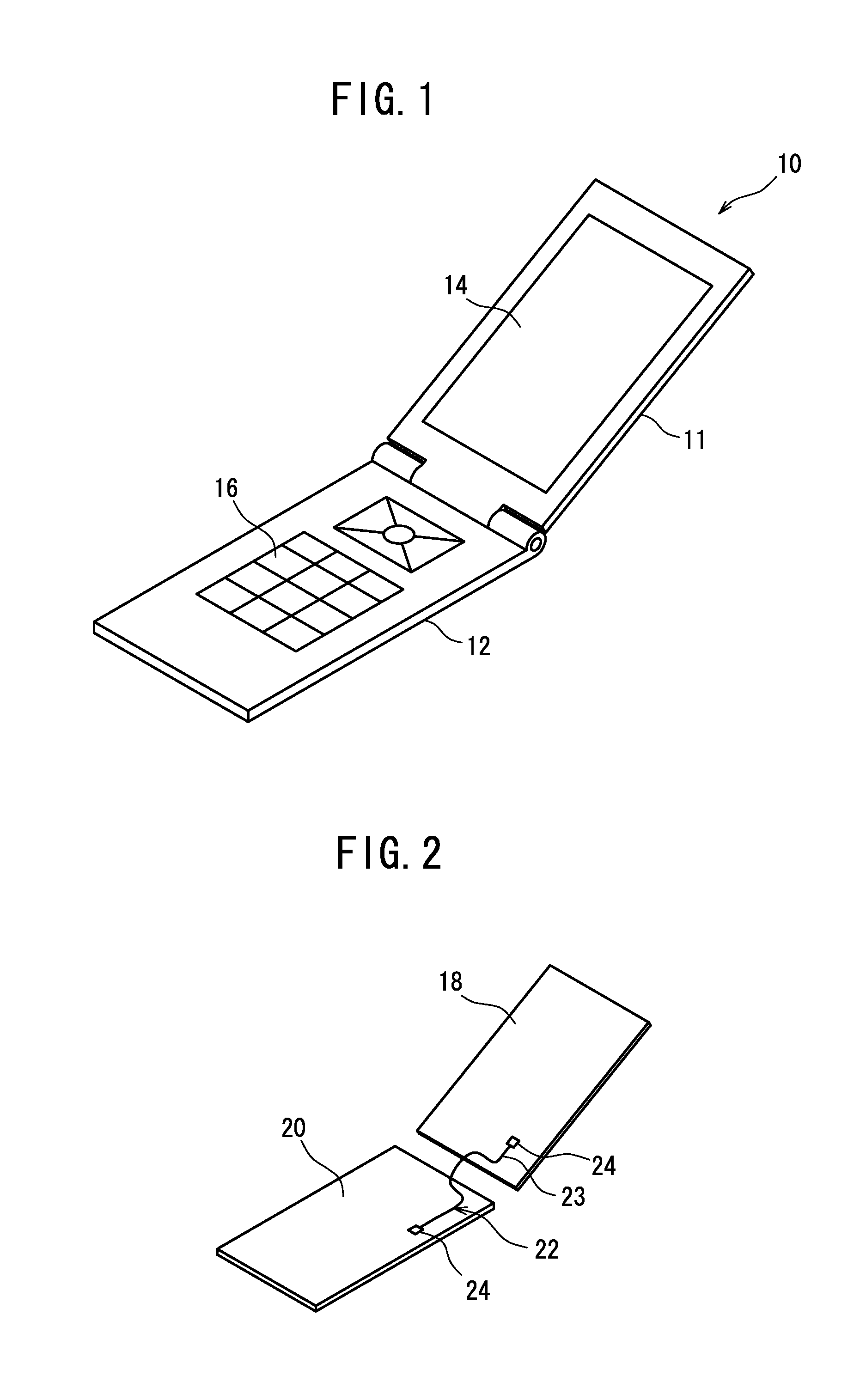
[0020]FIG. 1 is a perspective view schematically showing an outer appearance of a mobile phone 10. The mobile phone 10 is of, for example, a fold type, in which a first case 11 and a second case 12 are coupled via a hinge. A liquid crystal panel 14 is placed on the first case 11, and buttons 16 are placed on the second case 12, and a user is capable of obtaining information from an image displayed on the liquid crystal panel 14.

[0021]FIG. 2 shows a first motherboard 18 and a second motherboard 20 disposed in the first case 11 and the second case 12 respectively. Though not shown, electric components forming a driving circuit of the liquid crystal panel 14 are mounted on the first motherboard 18, and electric components forming an input circuit connected to the buttons 16, a communication circuit, and an image processing circuit are mounted on the second motherboard 20.
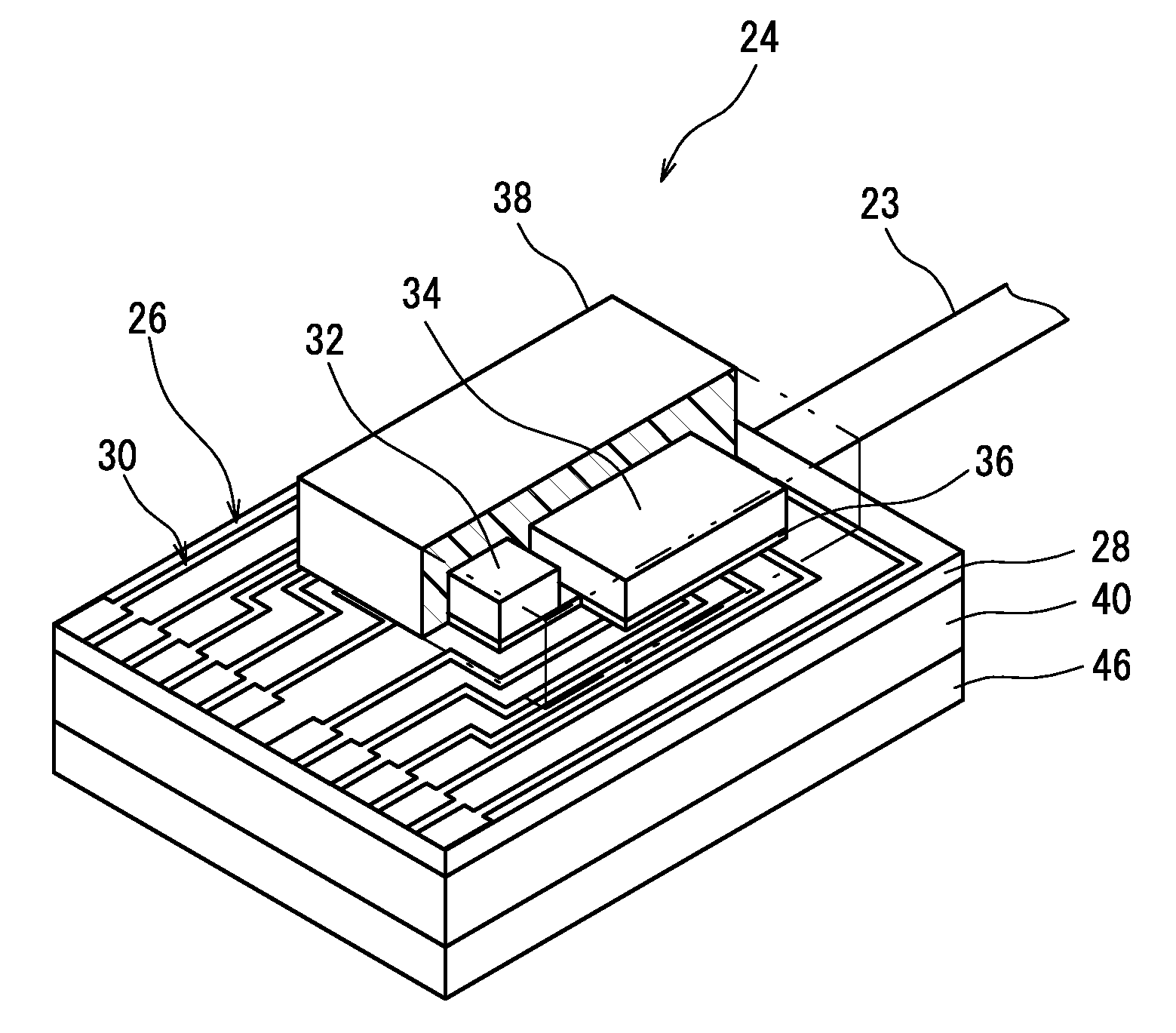
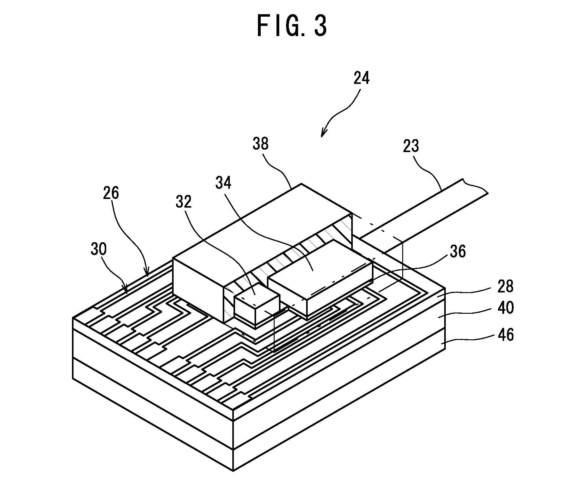
[0022]The...


PUM


Abstract

A photoelectric conversion module includes: an IC chip and a photoelectric conversion element mounted on one surface of a circuit board having a light transmitting property and flexibility; an optical fiber having a tip portion disposed in a holding groove formed in a resin layer provided on another surface of the circuit board; a reinforcing member covering the holding groove; and an optical element optically coupling a tip of the optical fiber and the photoelectric conversion element via the circuit board. The holding groove has an open end at an end of the resin layer, the end of the resin layer being located on the IC chip side in terms of an arrangement direction of the IC chip and the photoelectric conversion element, and at least part of the tip portion of the optical fiber extends along the IC chip.

Description

BACKGROUND OF THE INVENTION[0001]1. Field of the Invention[0002]The present invention relates to a photoelectric conversion module.[0003]2. Description of the Related Art[0004]As transmission mediums, for example, in the connection between a server and a switch in a data center and in the connection between digital AV (audio visual) devices, optical fibers are also used in addition to metal wires. Further, in recent years, the use of optical fibers as transmission mediums, that is, optical interconnection, also in information processing devices such is as mobile phones and personal computers has been considered. Refer to Japanese Patent Application Laid-open No. 2009-21459, for instance.[0005]When the optical fiber is used, a photoelectric conversion module converting an electrical signal to an optical signal or converting an optical signal to an electrical signal is required. For example, a photoelectric conversion module disclosed in Japanese Patent Application Laid-open No. 2010-...

Claims


Application Information

Patent Timeline
Patent Type & Authority Applications(United States)
IPC IPC(8): G02B6/12
CPCG02B6/3652G02B6/3696H01L2224/16225G02B6/4281G02B6/4214
Inventor YASUDA, HIROKIHIRANO, KOUKISUNAGA, YOSHINORIYU, JUHYUN
Owner HITACHI CABLE
Why Eureka
Try Eureka