Infinite temperature control for heating element of a cooking appliance

a technology of temperature control and heating element, applied in the field of cooking appliances, can solve the problems of insufficient sensitive scale and limited overall adjustment scale, and achieve the effect of enabling precise control of the entire heating zon

Active Publication Date: 2005-08-25
MAYTAG
View PDF20 Cites 25 Cited by
  • Summary
  • Abstract
  • Description
  • Claims
  • Application Information

AI Technical Summary

Benefits of technology

[0008] The present invention is directed to a cooking appliance including a top surface which defines a cooktop. The cooktop includes at least one selectively controllable heating zone and an associated control element. More specifically, the heating zone includes first and second heating elements, with the control element being associated with establishing a desired temperature level for the heating zone.
[0009] In accordance with a preferred embodiment of the invention, the control element includes a home position and a temperature adjustment zone for establishing a desired cooking temperature for the heating zone. More specifically, rotation of the control element from the home position, across the temperature adjustment zone, in a first direction activates only the first heating element and, rotation of the control element from the home position, across the temperature adjustment zone, in a second direction activates both the first and second heating elements. In either case, the particular orientation of the control element relative to the temperature adjustment zone can establish a desired temperature of the first heating element or both the first and second heating elements.
[0010] In accordance with the most preferred embodiment of the invention, the cooking appliance includes a microcontroller operatively connected to the control element, and first and second relays operatively conne

Problems solved by technology

In any case, while effective at operating various heating elements 3-6, the overall adjustment scale is somewhat

Method used


Image

  • Infinite temperature control for heating element of a cooking appliance
  • Infinite temperature control for heating element of a cooking appliance
  • Infinite temperature control for heating element of a cooking appliance

Examples


Embodiment Construction

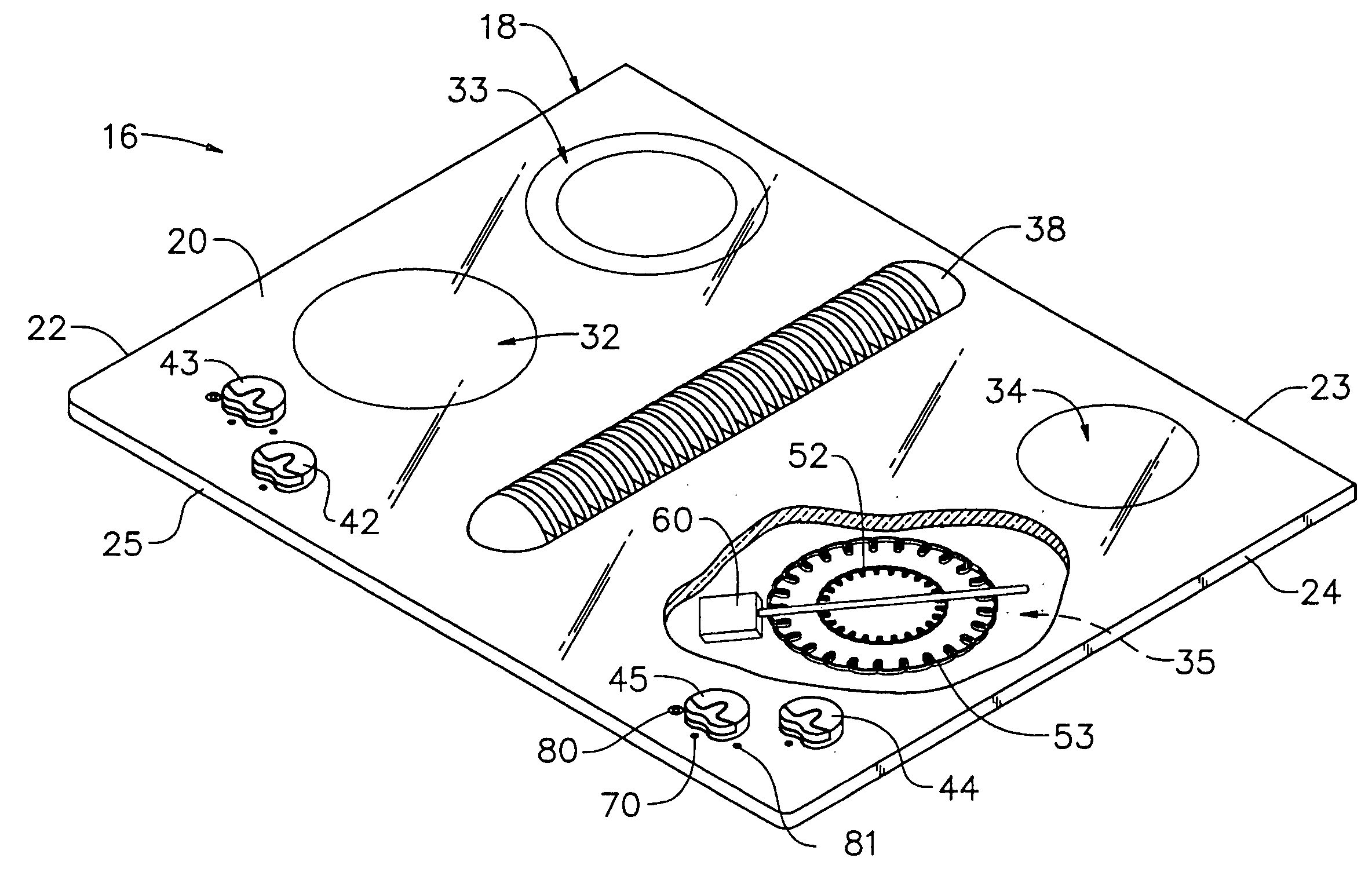
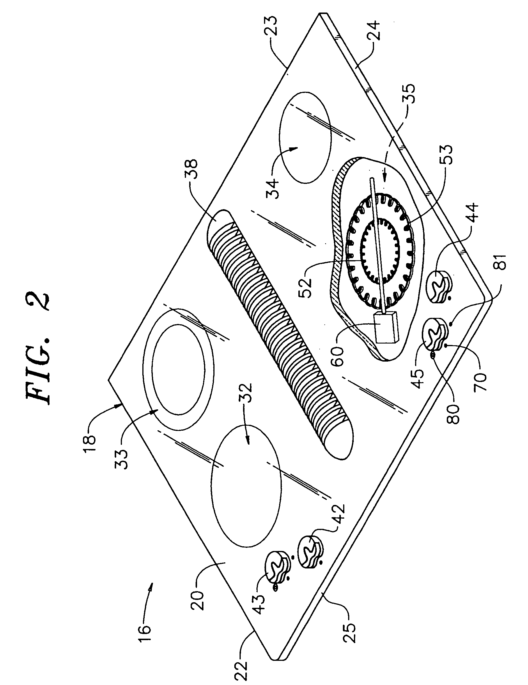
[0016] With initial reference to FIG. 2, a cooking appliance constructed in accordance with the present invention is generally shown at 16. Although the actual cooking appliance into which the present invention may be incorporated can vary, the invention is shown in connection with cooking appliance 16 depicted as a smooth surface cooktop 18. However, it should be understood that the present invention is not limited to this particular configuration and can be incorporated into various types cooking appliances, including free standing ranges, slide-in ranges and the like. In the embodiment shown, cooktop 18 includes a top surface 20, defined by outer peripheral edge portions 22-25, having arranged there about a plurality of cooking zones 32-35.

[0017] In a manner known in the art, a downdraft fan unit 38 is shown centrally positioned upon top surface 20 between the plurality of cooking zones 32-35. In general, downdraft fan unit 38 is provided to remove smoke and / or other food efflue...


PUM


Abstract

A cooking appliance includes a cooktop having at least one heating zone having first and second heating elements and a control element for setting a desired cooking temperature for the heating zone. When the control element is rotated in a first direction, only the first heating element will be activated and, when rotated in a second direction, both the first and second heating elements are activated. The control element includes a variable resistor that changes resistance as the control element is rotated through nearly 360° to alter the operational state of the heating element(s). A controller senses the change in resistance and determines in which direction the control element is rotated so as to activate the appropriate heating element(s).

Description

BACKGROUND OF THE INVENTION [0001] 1. Field of the Invention [0002] The present invention pertains to the art of cooking appliances and, more particularly, to an infinite temperature control element for selectively operating a heating zone arranged on a cooking appliance cooktop. [0003] 2. Discussion of the Prior Art [0004] Infinite temperature controls are known in the art of cooking appliances for controlling heating elements or zones arranged on cooktops of the cooking appliances. Typically, a control element or knob is rotated from an “off” position, across a temperature selection zone, to establish a desired operating temperature for a heating element. The temperature zone ranges from a low setting, positioned in a beginning portion of the rotation of the control knob, to a maximum setting positioned at an end portion of the rotation of the control knob. That is, the control knob provides infinite adjustment over a finite range so that the control knob actually rotates over a r...

Claims


Application Information

Patent Timeline
IPC IPC(8): F24C7/06F24C7/08F24C15/10H05B3/02H05B3/68
CPCF24C15/105H05B2213/07H05B3/68F24C7/083
Inventor STERLING, MARGARET M.
Owner MAYTAG
Why Eureka
Try Eureka