Control device for antenna matching circuit

a control device and antenna matching technology, applied in the field of wireless communication, can solve the problems of difficult for the matching circuit to flexibly adjust the signal energy cannot be effectively radiated from the antenna or supplied to the internal circuit, and the difficulty of adjusting the antenna impedance according to the matching circui

Active Publication Date: 2005-08-25
FUJITSU LTD
View PDF16 Cites 84 Cited by
  • Summary
  • Abstract
  • Description
  • Claims
  • Application Information

AI Technical Summary

Benefits of technology

[0008] The present invention was conceived to overcome the above-described problems, and it is an object of the in

Problems solved by technology

It is necessary for radio communication equipment to implement impedance matching between the antenna and the internal circuit; otherwise, the signal energy cannot be effectively radiated from the antenna or supplied to the internal circuit.
The matching circuit disclosed in JPA 8-148960 adjusts the impedance between only two levels, and therefore, it is difficult for this matching circuit to flexibly adjust the antenna impedance according to the status of use.
However, these circuits require a dedicated digital processor for adjusting the impedance of the high-frequency variable element.
Accordingly,

Method used


Image

  • Control device for antenna matching circuit
  • Control device for antenna matching circuit
  • Control device for antenna matching circuit

Examples


Embodiment Construction

[0018] The preferred embodiments of the invention are next described with reference to the accompanying drawings.

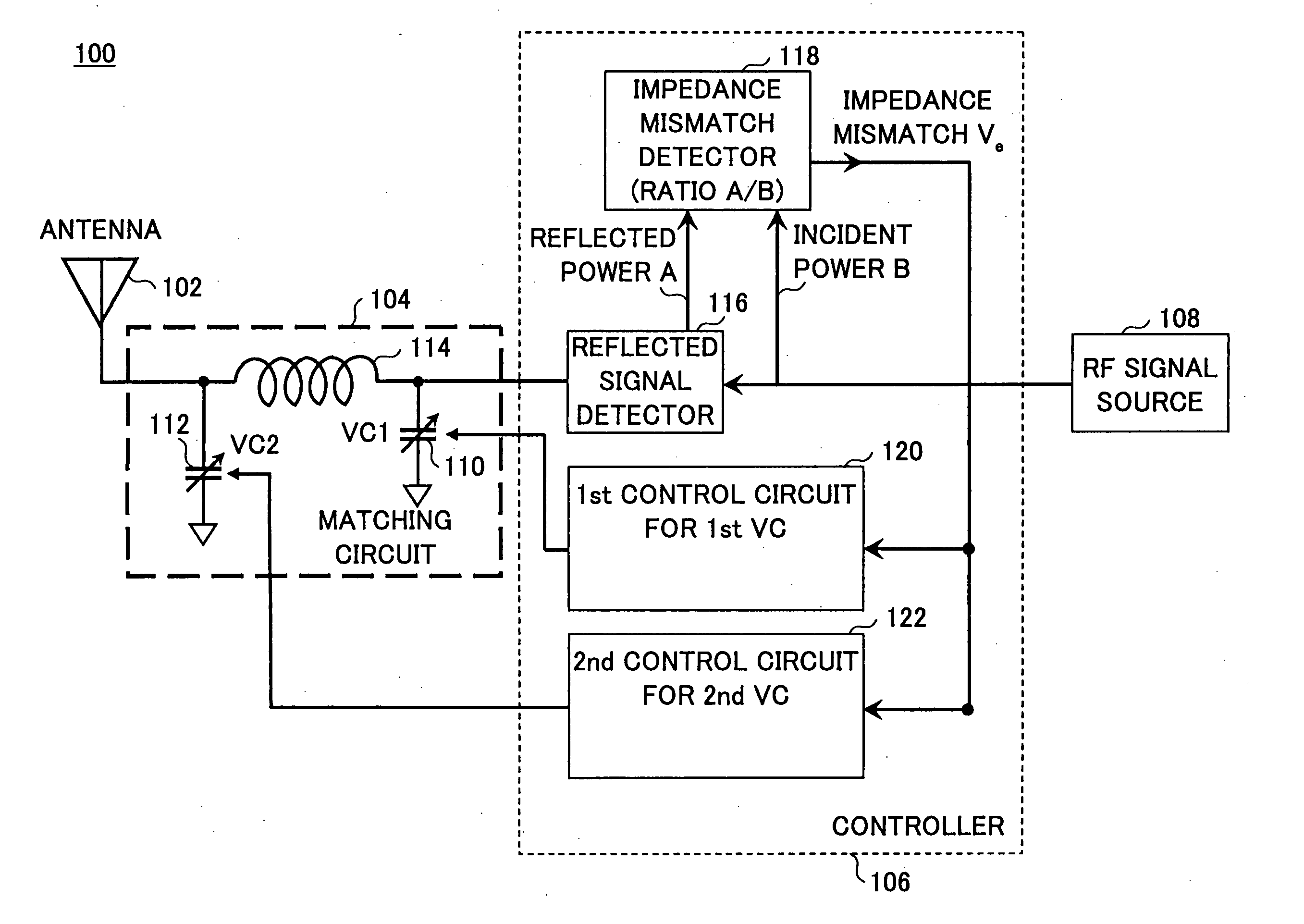
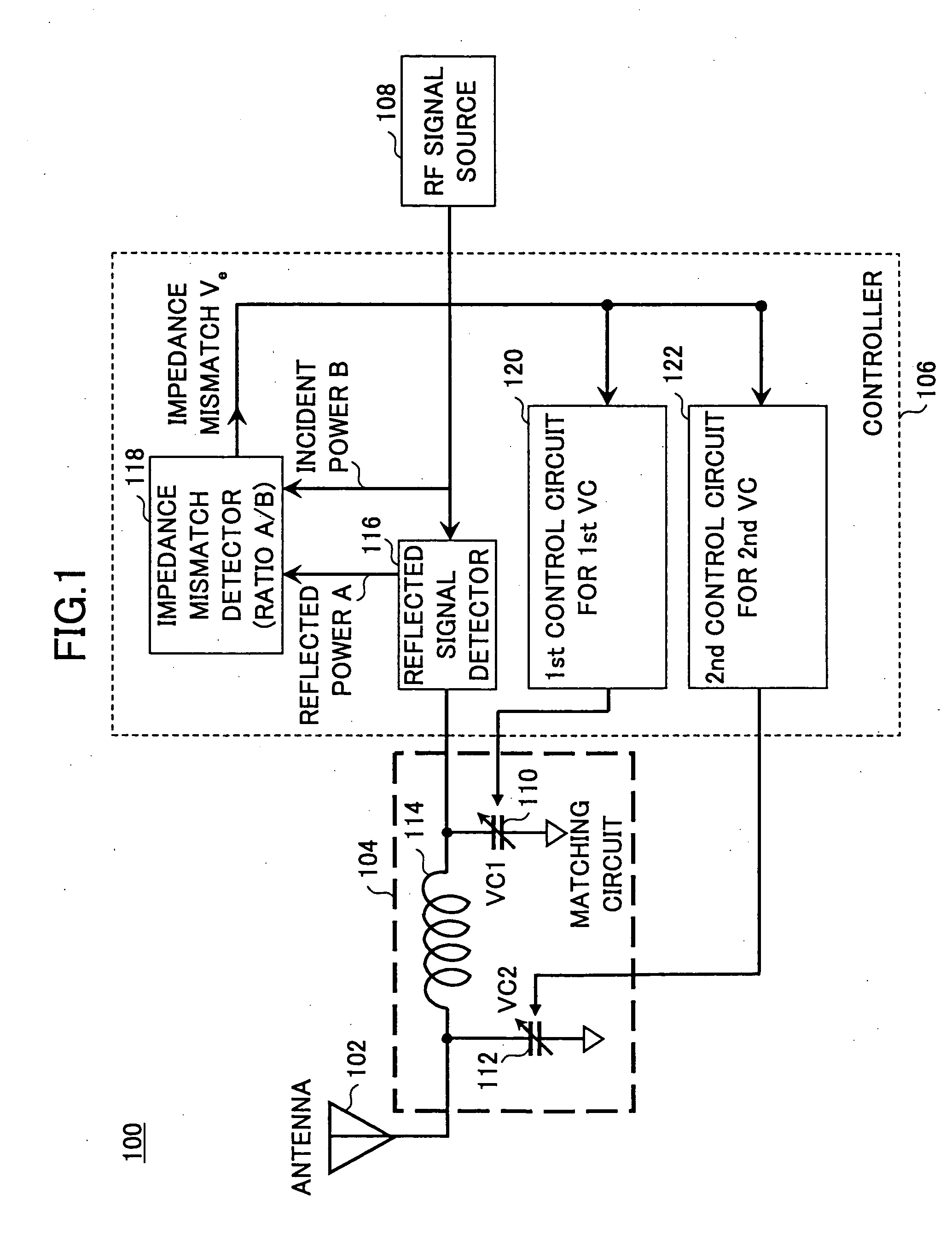
[0019]FIG. 1 is a block diagram illustrating a part of a radio communication equipment set having a control device for an antenna matching circuit, according to an embodiment of the invention. The radio communication equipment 100 includes an antenna 102, an antenna matching circuit 104, a controller 106, and an RF signal source 108. The matching circuit 104 has a first varactor capacitor (a capacitor using a varactor diode) 110, a second varactor capacitor 112, and a coil 114. The controller 106 has a reflected signal detector 116, an impedance mismatch detector 118, a first controlling circuit 120 for controlling the first varactor capacitor 110, and a second controlling circuit 122 for controlling the second varactor capacitor 112.

[0020] The matching circuit 104 implements impedance matching between the antenna and other processing circuits in the radio communication...


PUM


Abstract

A control device for an antenna matching circuit is configured to output an adjusting signal for changing impedance of an element in the antenna matching circuit based on change over time in signal power ratio of a reflected signal from the antenna matching circuit to an incident signal to the antenna matching circuit.

Description

BACKGROUND OF THE INVENTION [0001] The present invention generally relates to the technical field of wireless communication, and more particularly, to a control device for regulating the circuit constant of an antenna matching circuit. [0002] It is necessary for radio communication equipment to implement impedance matching between the antenna and the internal circuit; otherwise, the signal energy cannot be effectively radiated from the antenna or supplied to the internal circuit. [0003] In mobile communication, the input / output impedance of the antenna varies depending on the environment in actual use. For instance, in receiving a radio wave, the input impedance of the antenna of radio communication equipment placed on a desk differs from the input impedance of that radio communication equipment held in hand. For this reason, radio communication equipment is furnished with an a antenna matching circuit for adjusting the input impedance of the antenna so as to equal or approximate th...

Claims


Application Information

Patent Timeline
IPC IPC(8): H03H7/40H01Q23/00H03H7/38H04B1/04
CPCH04B1/0458H01Q23/00
Inventor IDA, ICHIROUTAKADA, JUN-ICHITODA, TAKESHIOISHI, YASUYUKI
Owner FUJITSU LTD
Why Eureka
Try Eureka