Connector

Active Publication Date: 2005-08-25
SUMITOMO WIRING SYST LTD
View PDF6 Cites 22 Cited by
  • Summary
  • Abstract
  • Description
  • Claims
  • Application Information

AI Technical Summary

Benefits of technology

[0010] The invention is directed to a connector with first and second housings that are connectable with each other. A resiliently deformable lock arm is provided on one housing and an interlocking portion is provided on the other housing. The lock arm slides in contact with the interlocking portion in the process of connecting the housings and is deformed temporarily. However, the lock arm restores resiliently to engage the interlocking portion when the housings are connected properly. A partial sliding contact is provided on at least one of facing surfaces of the lock arm and the interlocking portion and slides in contact with the mating facing surface in the connecting process. The sliding contact area is smaller than the width of the facing surface, and frictional resistance between the facing surfaces during the connecting process is reduced. As a result, the connecting operation is easier.
[0011] The housing preferably has at least one cavity and a resiliently deformable lock is formed in the cavity. A terminal fitting can be inserted into the cavity and deforms the lock during the insertion. However, the lock restores resiliently to engage an engageable portion of the terminal fitting when the terminal fitting reaches a proper depth. A partial sliding contact is provided on one of facing surfaces of the lock and the engageable portion and slides in contact with the mating facing surface during connection. The partial sliding contact preferably slides in contact with the mating facing surface when the lock slides in contact with the engageable portion. A sliding contact area is smaller than a width of the facing surface. Therefore, frictional resistance between the facing surfaces during insertion is reduced, and the insertion is easier.
[0012] At least one facing surface may be at least partly arcuate and the partial sliding contact portion may be a linear area on the arcuate surface. The partial sliding contact preferably slides in contact with the mating facing surface along connecting and separating directions. The linear configuration of the sliding contact area along the connecting and separating directions ensures a low frictional resistance.
[0015] The outer surface of the first housing preferably has curved corners and substantially straight surfaces connecting the curved corners. The loose movement-preventing portion preferably is on the straight surface. The dimensions of the loose movement-preventing portion can be controlled more accurately on the straight surface. Accordingly, contact pressure on the second housing during the connecting operation is controlled more accurately than if the loose movement-preventing portion was on a curved surface.
[0017] The second housing preferably has a resilient member for preventing the housings from making loose movements in the connecting and separating directions and in directions intersecting the connecting and separating directions. The front end of the first housing preferably compresses the resilient member as the housings are connected.

Problems solved by technology

However, a wider lock arm generates a larger frictional resistance during a connecting process.
However, a wider lock would increase the force required to insert the terminal fitting into the cavity.
A connector used in an engine compartment of an automotive vehicle is subjected to frequent vibration.

Method used


Image

  • Connector
  • Connector
  • Connector

Examples


first embodiment

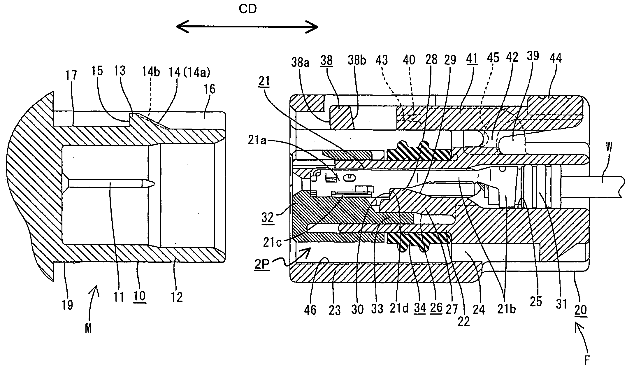
[0033] the invention is described with reference to FIGS. 1 to 9 and relates to a locking construction of a watertight connector. The watertight connector has male and female connectors M, F connectable with each other along a connecting direction CD. Sides of the connectors F, M to be connected are referred to as the front sides and reference is made to all the figures except FIGS. 4, 7 and 9 concerning the vertical direction.

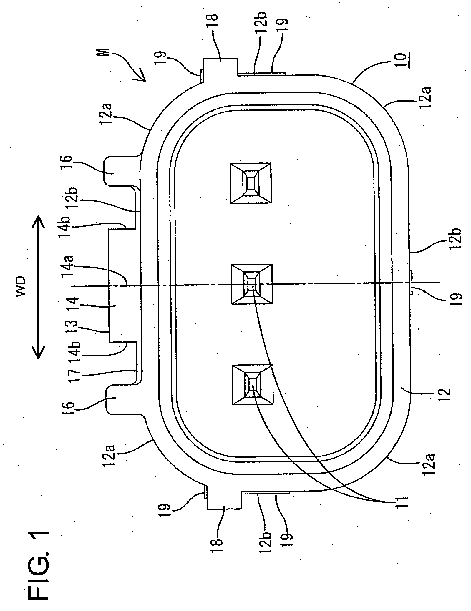
[0034] The male connector M includes a synthetic resin male housing 10 that is coupled directly to a wall of an apparatus, as shown in FIGS. 1, 3 and 4. Three male terminal fittings 11 are embedded in the male housing 10 to define a substantially side-by-side array along a width direction WD. A rectangular tubular receptacle 12 of the male housing 10 projects forward from the apparatus and surrounds front ends of the male terminal fittings 11. An interlocking portion 13 projects up substantially in the widthwise middle of the upper surface of the receptacle 12...

third embodiment

[0066] In the third embodiment, three or more flat surfaces may be formed on the front of the interlocking portion and / or the rear of the lock, thereby providing a plurality of meeting portions of the flat surfaces. In such a case, the sliding contact area may be a surface along forward and backward directions provided that it partly comes into sliding contact with the mating part.

[0067] The forms of the lock arm and the interlocking portion may be changed. For example, the male housing may have the lock arm while the female housing may have the interlocking portion, or the unlocking arm may be dispensed with. Similarly, the forms of the lock and the terminal fitting may be changed. Further, male terminal fittings may be accommodated in the male housing, and the invention may be applied to locks in the male housing. The invention is also applicable to nonwatertight connectors.

[0068] The number, positions and shapes of the loose movement preventing portions may be changed in the for...


PUM


Abstract

A female housing (20) has a resiliently deformable lock arm (38), whereas a male housing (10) is provided with an interlocking portion (13). During the connection of the two housings (10, 20), the lock arm (38) is temporarily deformed while being held in sliding contact with the interlocking portion (13). When the two housings (10, 20) are properly connected, the lock arm (38) is restored resiliently to engage the interlocking portion (13). A front surface (14) of the interlocking portion (13) to face the lock arm (38) during a connecting process is arcuate. Thus, only a widthwise middle (14a) of the interlocking portion (13) slides in contact with the lock arm (38) during a connecting operation.

Description

BACKGROUND OF THE INVENTION [0001] 1. Field of the Invention [0002] The invention relates to a connector. [0003] 2. Description of the Related Art [0004] U.S. Pat. No. 5,336,540 discloses a connector with male and female housings that are connectable with each other. The female housing has a lock arm and a male housing has an engaging portion that is engageable with the lock arm. The lock arm moves onto the front surface of the engaging portion during connection of the housings and deforms temporarily. The lock arm restores resiliently to engage the rear surface of the engaging portion when the housings are connected properly. [0005] The housings have cavities for receiving terminal fittings and locks are formed in the cavities. The outer wall of the terminal fitting pushes the rear surface of the lock to deform the lock temporarily as the terminal fitting is inserted into the cavity. The lock is restored resiliently and engages the outer wall of the terminal fitting when the termin...

Claims


Application Information

Patent Timeline
IPC IPC(8): H01R3/00H01R13/422H01R13/52H01R13/627H01R13/639
CPCH01R13/4223H01R13/6272H01R13/5221
Inventor FUKATSU, YUKIHIROICHIDA, KIYOFUMITOYODA, YUKIHIROOKAYASU, YASUSHI
Owner SUMITOMO WIRING SYST LTD
Why Eureka
Try Eureka