Bicycle derailleur with a motor disposed within a linkage mechanism

a technology of linkage mechanism and derailleur, which is applied in the field of bicycle derailleur, can solve the problems of derailleur being damaged or destroyed, derailleur being struck,

Active Publication Date: 2005-08-25
SHIMANO INC
View PDF24 Cites 42 Cited by
  • Summary
  • Abstract
  • Description
  • Claims
  • Application Information

AI Technical Summary

Problems solved by technology

This, in turn, creates the risk that the derailleur may be struck by rocks or other obstacles when riding in rough terrain, or that the derailleur is damaged or destroyed if the bicycle falls over.
Furthermore, sometimes

Method used


Image

  • Bicycle derailleur with a motor disposed within a linkage mechanism
  • Bicycle derailleur with a motor disposed within a linkage mechanism
  • Bicycle derailleur with a motor disposed within a linkage mechanism

Examples


Embodiment Construction

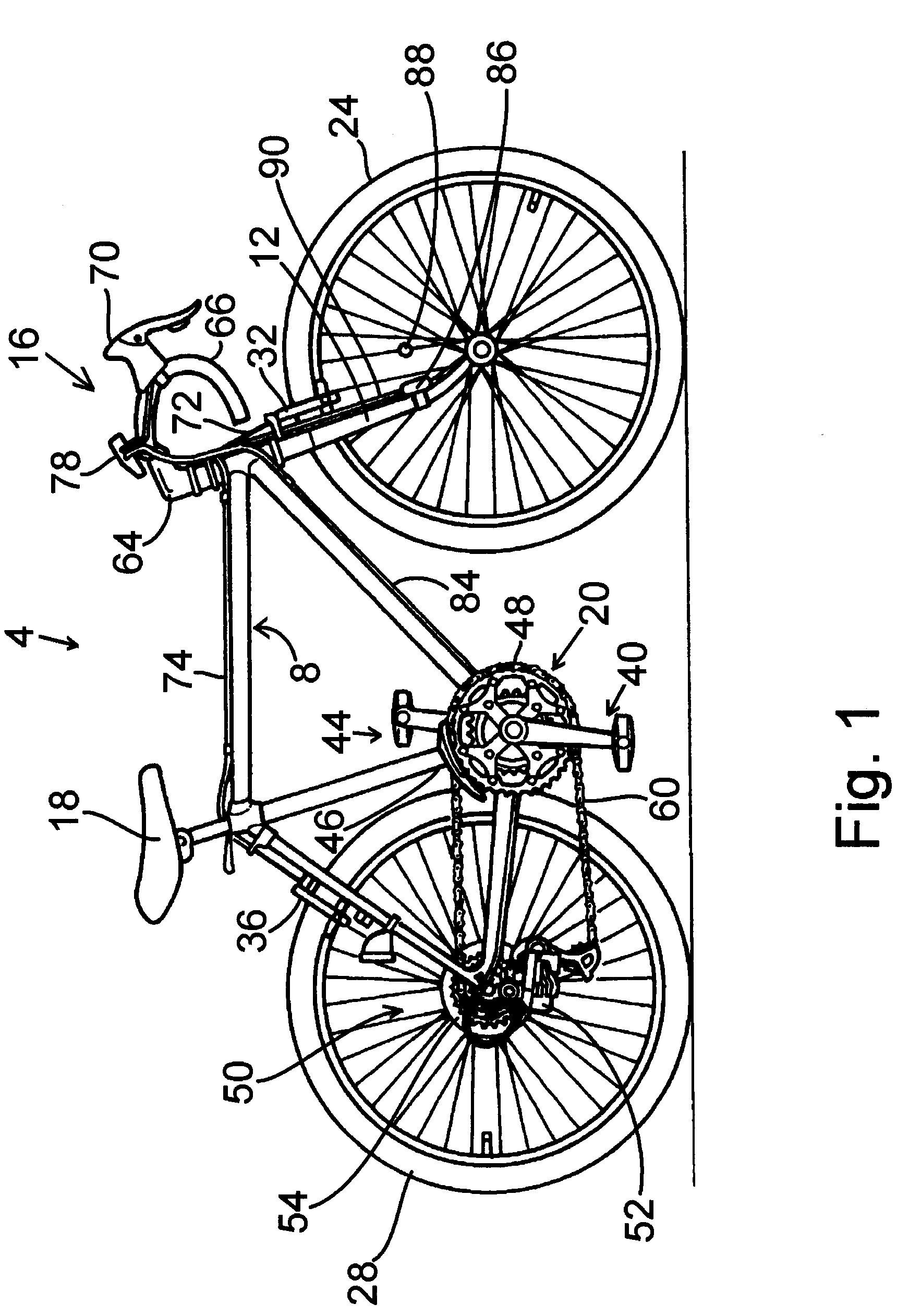
[0020]FIG. 1 is a side view of a particular embodiment of a bicycle 4. Bicycle 4 comprises a frame body 8 constructed by welding tubing together in a conventional double diamond configuration. A front fork 12 is mounted to the front of frame body 8 for rotation around an inclined axis, and a handlebar assembly 16 is mounted to the top of front fork 12. A saddle 18 is mounted to the upper middle part of frame body 8, a drive mechanism 20 is mounted to the lower part of frame body 8, a front wheel 24 is rotatably mounted to the bottom of front fork 12, and a rear wheel 28 is rotatably mounted to the rear of frame body 8. A front brake mechanism 32 is used to brake front wheel 24, and a rear brake mechanism 36 is used to brake rear wheel 28.

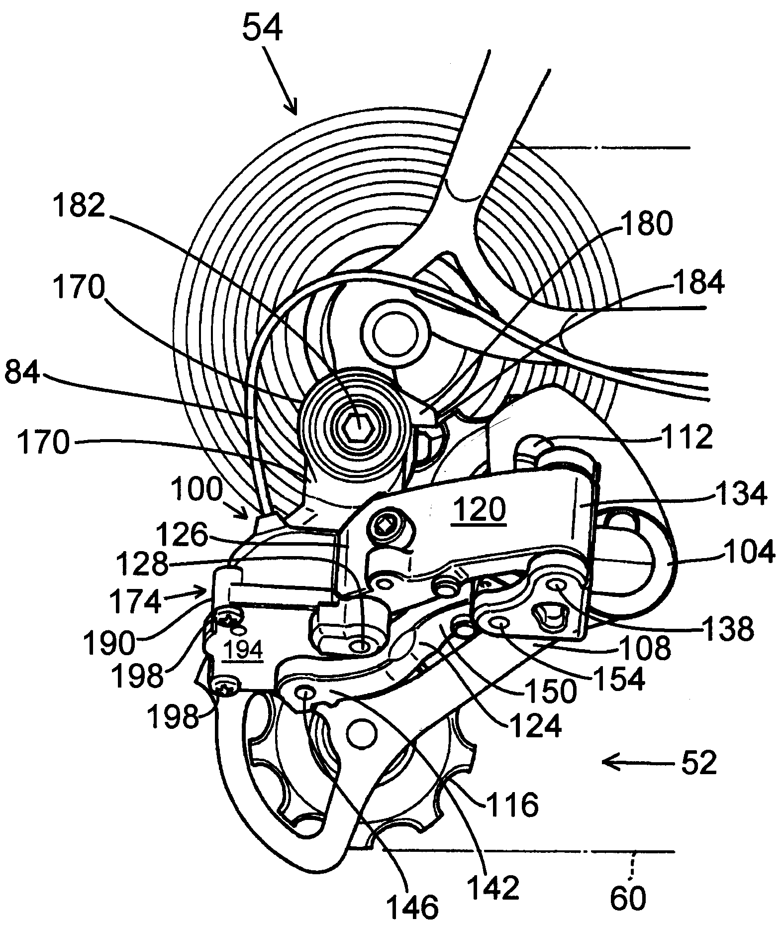
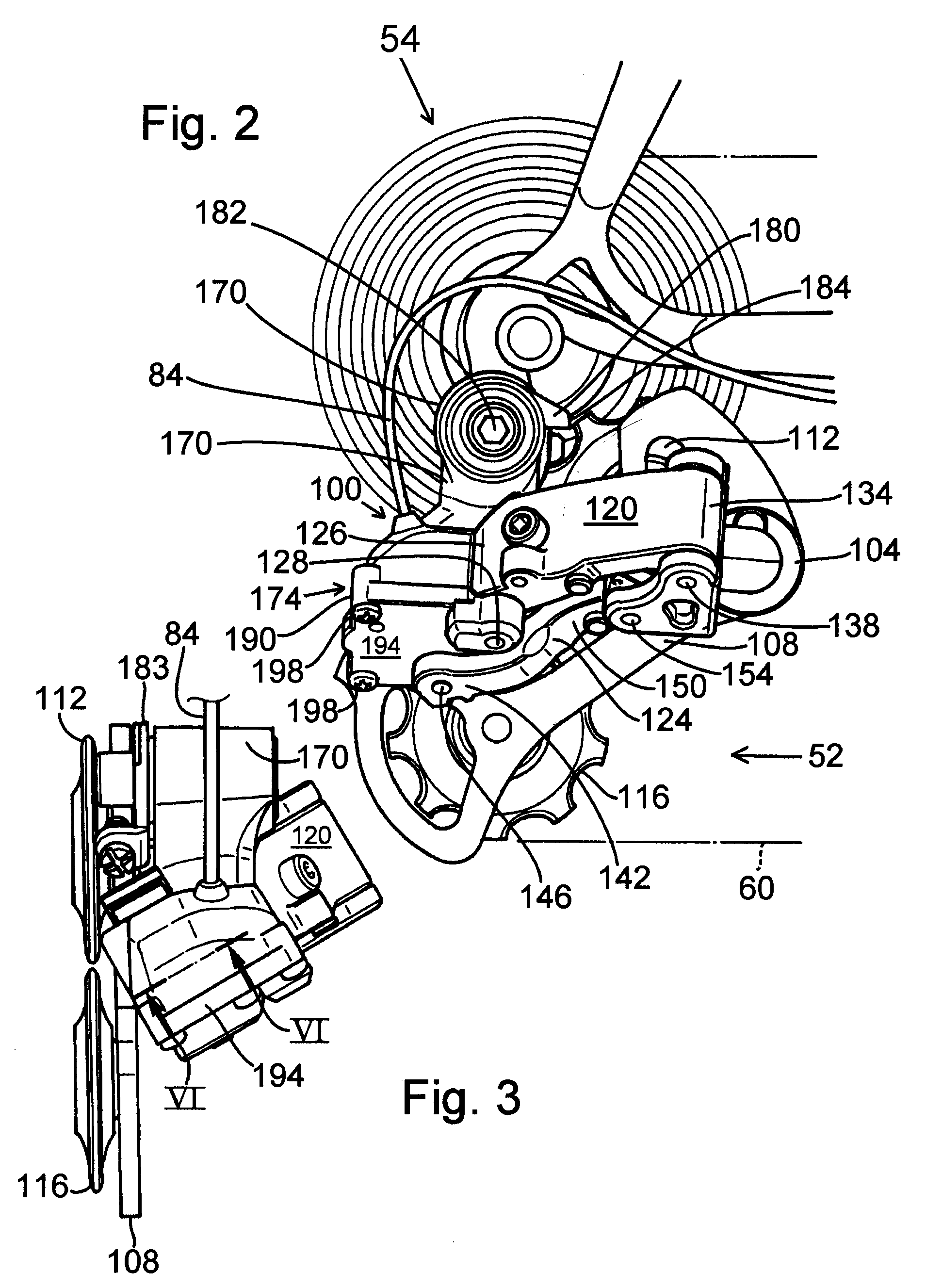
[0021] Drive mechanism 20 comprises a pedal crank assembly 40 rotatably mounted at the bottom bracket of frame body 8, a front transmission 44 including a front derailleur 46 mounted to frame body 8 and a plurality of (e.g., two) sprockets 48 is mo...


PUM


Abstract

A bicycle derailleur comprises a base member, a movable member for supporting a chain guide, a first link member pivotably coupled to the base member and to the movable member through respective first and second link pins, a second link member pivotably coupled to the base member and to the movable member through respective third and fourth link pins, and a motor having a drive shaft that defines a drive shaft vector. The first through fourth link pins define edges of a phantom space, wherein straight continuous phantom lines connecting ends of the first through fourth link pins in a non-crossing manner define remaining edges of the phantom space. At least a part of the primary motor housing is disposed in the phantom space, and the drive shaft vector points away from a plane containing the second and fourth link pins.

Description

BACKGROUND OF INVENTION [0001] The present invention is directed to bicycles and, more particularly, to a motorized bicycle derailleur. [0002] Many current bicycles have electronically controlled bicycle components. For example, some bicycles include automatic transmissions wherein electronically motorized front and rear derailleurs are automatically controlled by a microcomputer based on bicycle speed. One type of motorized derailleur includes a motor that is spaced apart from the derailleur and connected to the derailleur by a conventional Bowden cable, wherein the motor pulls and releases the inner wire of the Bowden cable to operate the derailleur. Another type of motorized derailleur integrates the motor with the derailleur so that the motor drive shaft directly moves the derailleur linkage mechanism. Such a configuration eliminates the requirement of a Bowden cable, thus making the overall derailleur mechanism more compact. [0003] While a derailleur with an integrated motor ha...

Claims


Application Information

Patent Timeline
IPC IPC(8): B62M9/1242B62M25/08B62M9/122
CPCB62M9/122Y10T74/18512B62M25/08B62M9/1242
Inventor FUKUDA, MASAHIKO
Owner SHIMANO INC
Why Eureka
Try Eureka