

Sheet processor and image-forming apparatus
a technology of image processing and sheet paper, applied in the direction of electrographic process, instruments, transportation and packaging, etc., to achieve the effect of fine folding portion appearan
- Summary
- Abstract
- Description
- Claims
- Application Information
AI Technical Summary
Benefits of technology
Problems solved by technology
Method used
Image

Examples
first embodiment
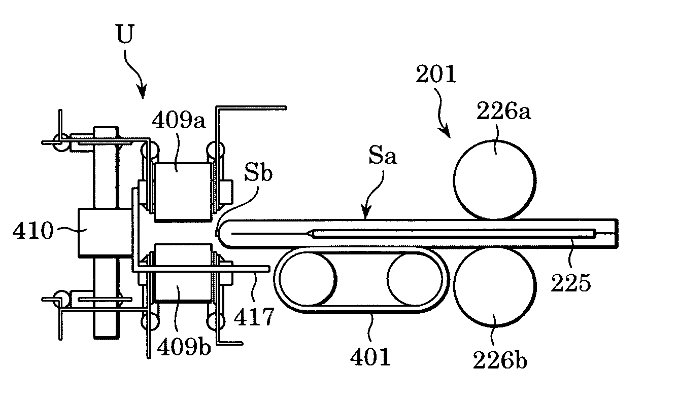
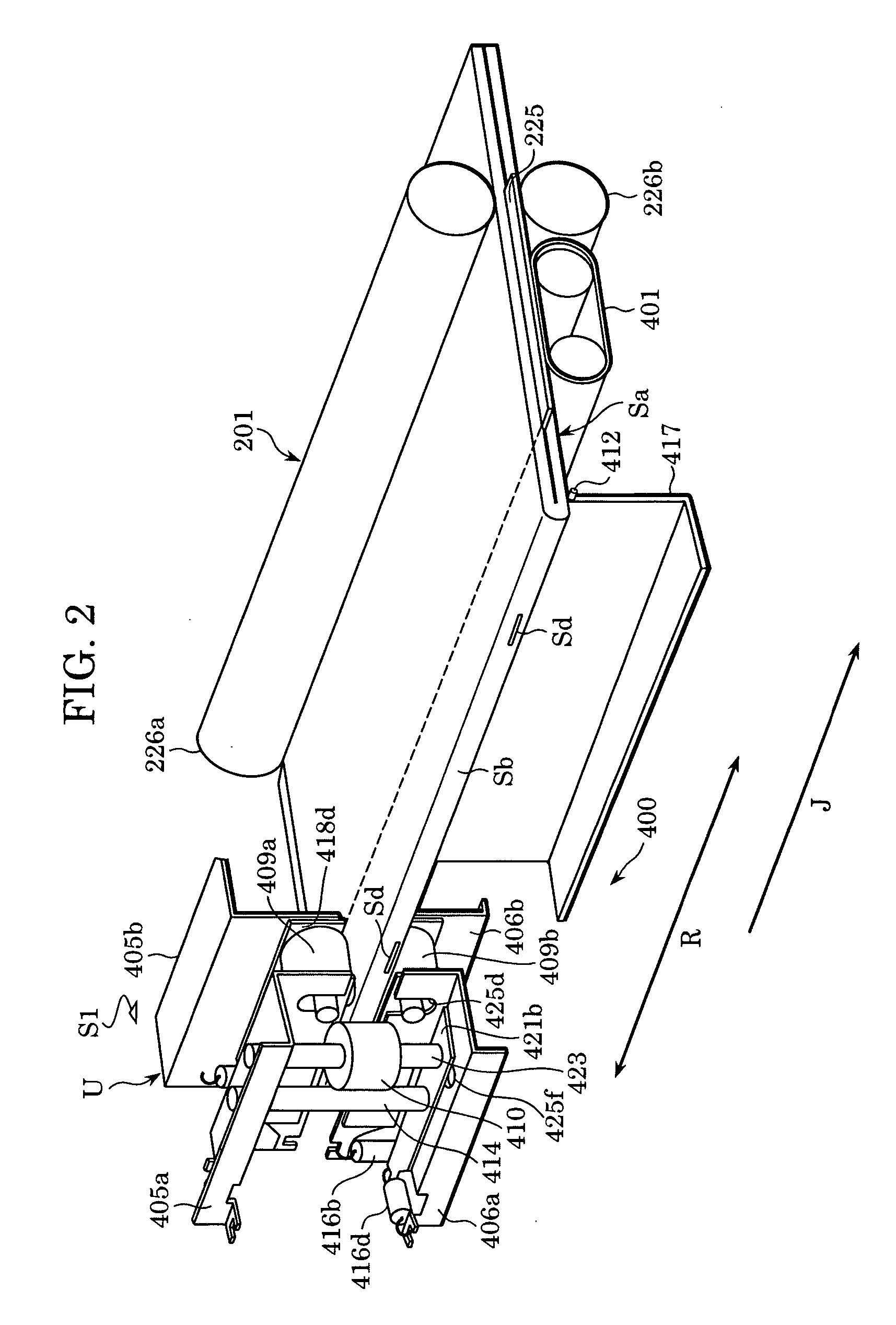
[0055] The structure of the folded-portion processing device 400 will now be described with reference to FIGS. 2 to 6. A stopper plate 417 shown in FIG. 2 is provided for positioning the leading end of the folded batch of sheets, i.e. the folded edge of the batch, and is rotatably supported by a rotary shaft 412. The stopper plate 417 is rotatable vertically about the rotary shaft 412 with a driving source (not shown).
[0056] Referring to FIGS. 3 and 4, a casing 413 having a substantially U-shaped cross section is provided for supporting an upper shaping-gripper 409a, a lower shaping-gripper 409b, a shaping roller 410, and other related components. In other words, the casing 413 and the above components supported by the casing 413, i.e. the upper shaping-gripper 409a, the lower shaping-gripper 409b, the shaping roller 410, and other related components, form a single folded-portion processing unit U for processing the folded portion of the batch of sheets. The folded-portion processi...
second embodiment
[0096] Furthermore, in the folded-portion processing device 1400 when a folded-portion processing unit U2 moves to the right in FIG. 12, the set of shaping grippers 409d and 409f on the right side precedes the shaping roller 410, whereas when the folded-portion processing unit U2 moves to the left, the set of shaping grippers 409c and 409e precedes the shaping roller 410. Consequently, whether the folded-portion processing unit U2 moves to the right or to the left, the shaping roller 410 is always preceded by either the set of shaping grippers 409d and 409f or the set of shaping grippers 409c and 409e. This means that the shaping roller 410 is capable of readily flattening the folded portion Sb by moving in either direction.
[0097] The second embodiment can ensure better shaping of the folded portion Sb of the batch Sa of sheets by allowing the folded-portion processing unit U2 to move back and forth several times.
[0098] In the first and second embodiments, the shaping grippers 409...
third embodiment
[0099]FIGS. 13 and 14 illustrate a folded-portion processing device 2400 according to a The folded-portion processing device 2400 is characterized in that the folded portion Sb (the spine) of the batch Sa is flattened by moving the batch Sa of sheets.
[0100] In the folded-portion processing device 2400, the batch Sa of sheets folded back by the set of folding rollers 226a and 226b and the pushing member 225 (not shown in FIGS. 13 and 14) is conveyed to a turning base 2401 via the folding rollers 226a and 226b. Subsequently, as shown in FIG. 13, the turning base 2401, which defines a conveying unit, rotates by about 90° around a point R so as to turn the batch Sa around by about 90°. The turning base 2401 then moves in the direction indicated by the large arrow in FIGS. 13 and 14. In the process of moving in the direction of the large arrow, the turning base 2401 allows the folded portion Sb of the batch Sa to receive the pressing force of the shaping roller 410 while the folded port...
PUM
| Property | Measurement | Unit |
|---|---|---|
| nipping force | aaaaa | aaaaa |
| pressing force | aaaaa | aaaaa |
| thickness | aaaaa | aaaaa |
Abstract
Description
Claims
Application Information