Smoke detection methods, devices, and systems

a detection method and smoke detection technology, applied in the field of remote monitoring residential systems, can solve the problems of high cost, difficult installation, and prone to interruption of connection, and achieve the effect of reducing the risk of accidental smoke detection

Inactive Publication Date: 2005-09-01
HUNT TECH INC
View PDF99 Cites 147 Cited by
  • Summary
  • Abstract
  • Description
  • Claims
  • Application Information

AI Technical Summary

Problems solved by technology

These home security systems, however, are often hardwired into the residence, which can be costly and quite difficult to install.
This connection is quite susceptible to interruption, either by accident or on purpose, and requires each residence to have a connection to the PSTN.

Method used


Image

  • Smoke detection methods, devices, and systems
  • Smoke detection methods, devices, and systems
  • Smoke detection methods, devices, and systems

Examples


Embodiment Construction

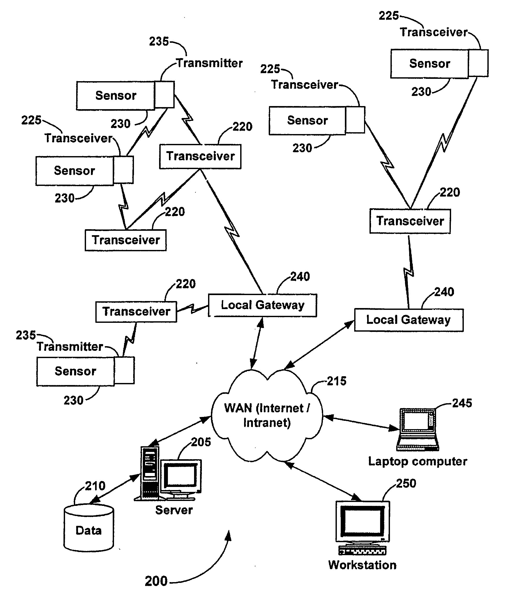
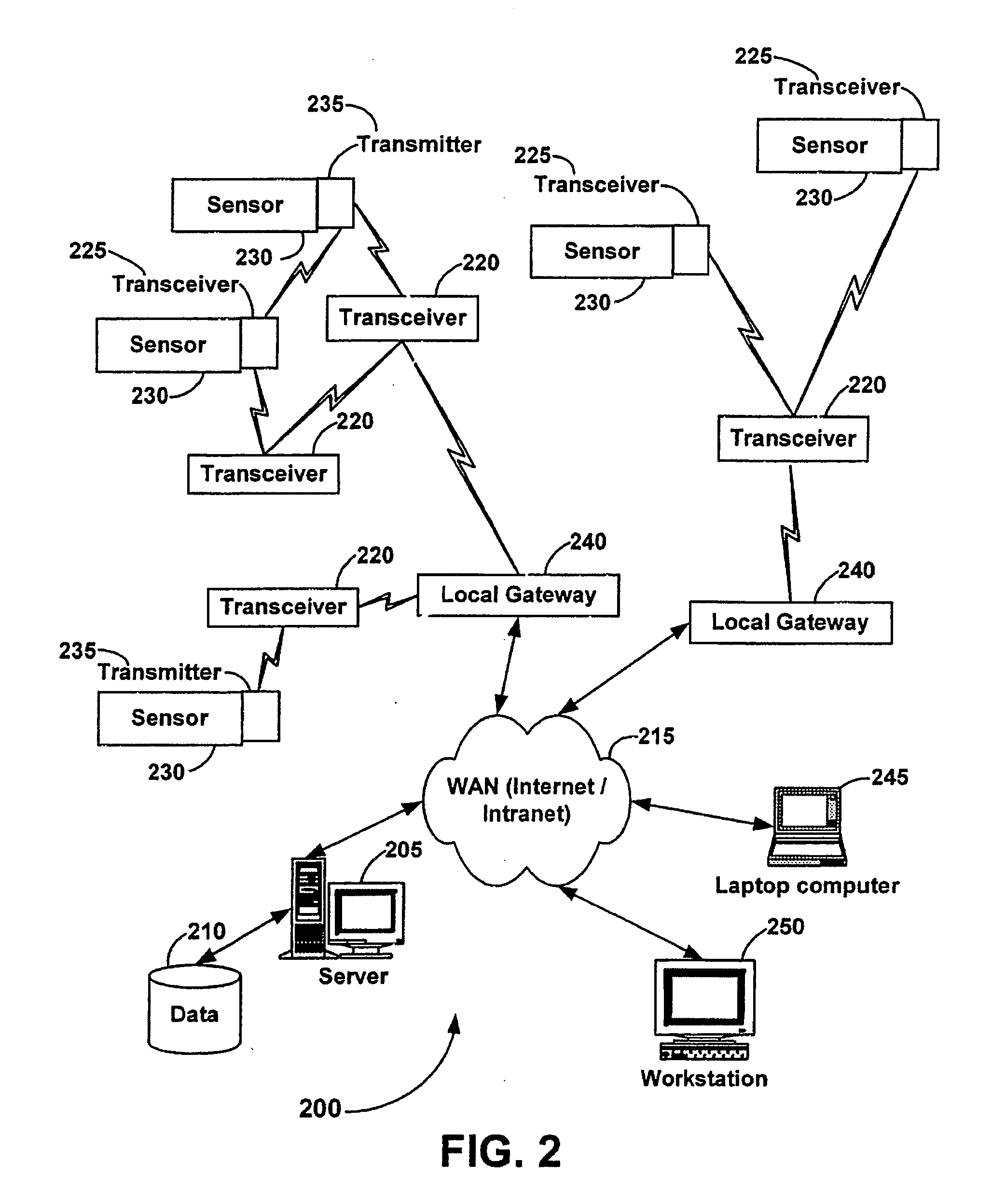
[0034] Having summarized the invention above, reference is now made in detail to the description of the invention as illustrated in the drawings. FIG. 2 is a schematic diagram illustrating a distributed data monitoring / control system suitable for home monitoring applications in accordance with an embodiment of present invention. As illustrated in FIG. 2, a distributed data monitoring / control system (DDMCS) in accordance with the present invention is identified generally by reference numeral 200. The DDMCS 200 may comprise one or more application servers 205 (one shown for simplicity of illustration), one or more data base servers 210, a WAN 215, a plurality of transceiver / repeaters 220, transceivers 225, sensors 230, transmitters 235, and at least one local gateway 240.

[0035] As is further illustrated in FIG. 2, a sensors 230 can be integrated such that it is communicatively coupled with a suitably configured RF transceiver / repeater 220, an RF transceiver 225, or an RF transmitter ...


PUM


Abstract

The present invention is directed to a system and method for accessing home monitoring devices remotely via a distributed wide-area network (WAN). More specifically, the present invention is directed towards a smoke detector system, which monitors for the presence of smoke and communicates the smoke condition to a remote location. The smoke detection system comprises a smoke detection device connected to a communication device. The smoke detection device outputs a signal or a change in a signal upon detection of smoke. This signal or change in signal is monitored by the communication device. The smoke condition is then communicated to the remote central location. Other embodiments are also claimed and described.

Description

CROSS-REFERENCE TO RELATED APPLICATIONS [0001] This application is a continuation of U.S. patent application Ser. No. 09 / 811,076, now U.S. Pat. No. ______, filed Mar. 16, 2001, and entitled “System and Method for Monitoring and Controlling Residential Devices”, which claims the benefit of U.S. Provisional Application Ser. No. 60 / 223,932, filed Aug. 9, 2000, and entitled “Design Specifications for a Smoke Detector Communication device”; and is a continuation-in-part of: U.S. patent application Ser. No. 09 / 790,150, now U.S. Pat. No. 6,522,974, filed Feb. 21, 2001, and entitled “System and Method for Monitoring and Controlling Residential Devices”; U.S. patent application Ser. No. 09 / 271,517, now abandoned, filed Mar. 18, 1999, and entitled, “System For Monitoring Conditions in a Residential Living Community”; U.S. patent application Ser. No. 09 / 439,059, now U.S. Pat. No. 6,437,692, filed Nov. 12, 1999, and entitled, “System and Method for Monitoring and Controlling Remote Devices”; U....

Claims


Application Information

Patent Timeline
Patent Type & Authority Applications(United States)
IPC IPC(8): G08B1/00G08B1/08G08B17/10
CPCG01V1/364G01V1/37G08B17/10H04W88/16H04M11/04H04W8/26H04W24/00G08B25/009G08B17/113
Inventor PETITE, THOMAS D.
Owner HUNT TECH INC
Why Eureka
Try Eureka