Method and apparatus for self-powered vehicular sensor node using magnetic sensor and radio transceiver

Inactive Publication Date: 2005-09-01
SENSYS NETWORKS
View PDF11 Cites 36 Cited by
  • Summary
  • Abstract
  • Description
  • Claims
  • Application Information

AI Technical Summary

Benefits of technology

[0012] The means for maintaining the clock count preferably is powered and runs most if not all the time, whereas the means for controlling and the means for operating are preferably powered only when a task is triggered. When the means for controlling and/or the means for operating are powered, they tend to consume much more power than the means for maintaining the clock count. The invention preferably minimizes power dissipation using this apparatus and its method of operation.
[0013] One or more computers, field programmable logic devices, and/or finite state machines may be included to implement these means. Preferably, the means for controll

Problems solved by technology

When the means for controlling and/or the means for operating are powered, they

Method used


Image

  • Method and apparatus for self-powered vehicular sensor node using magnetic sensor and radio transceiver
  • Method and apparatus for self-powered vehicular sensor node using magnetic sensor and radio transceiver
  • Method and apparatus for self-powered vehicular sensor node using magnetic sensor and radio transceiver

Examples


Example

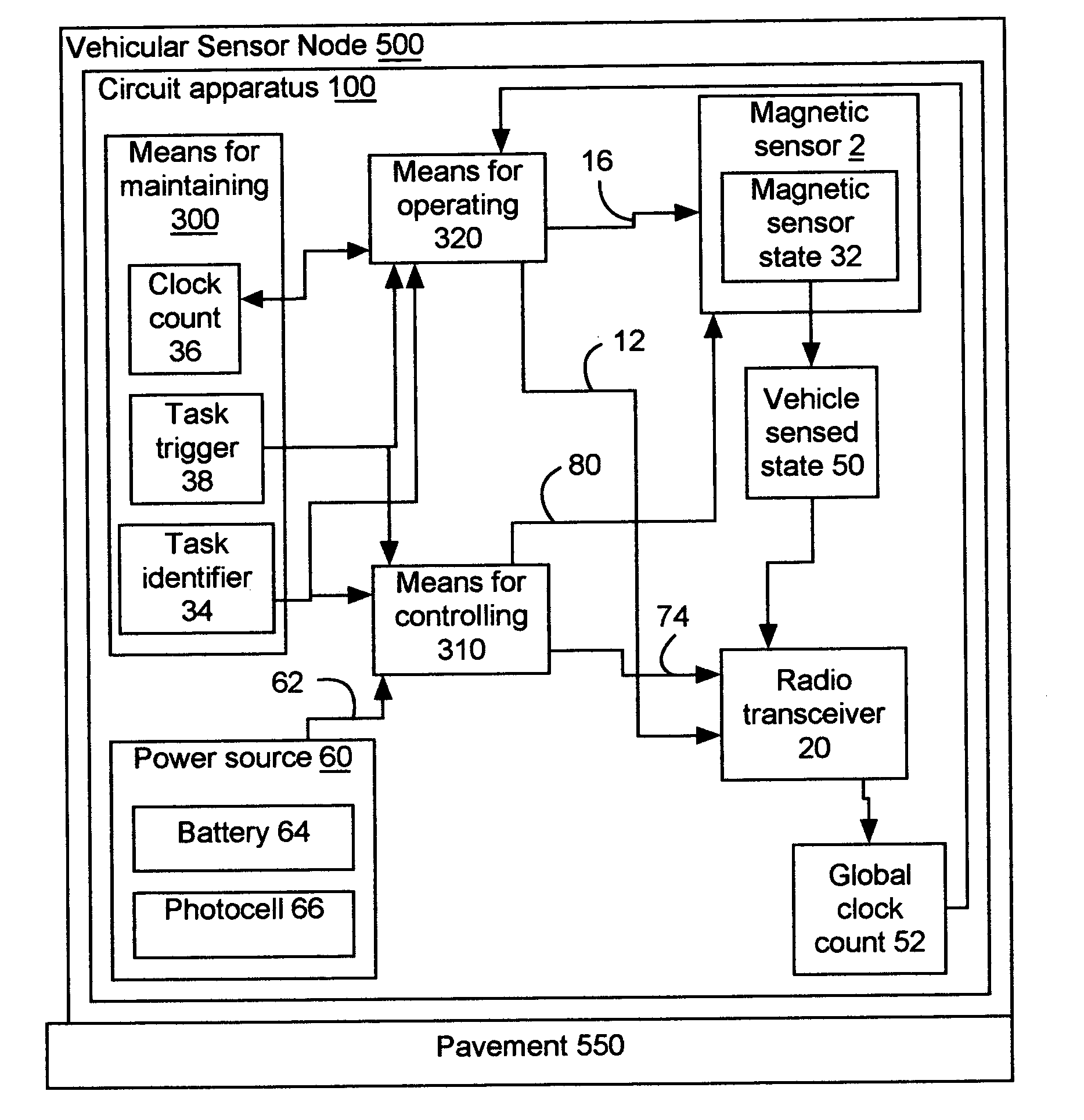
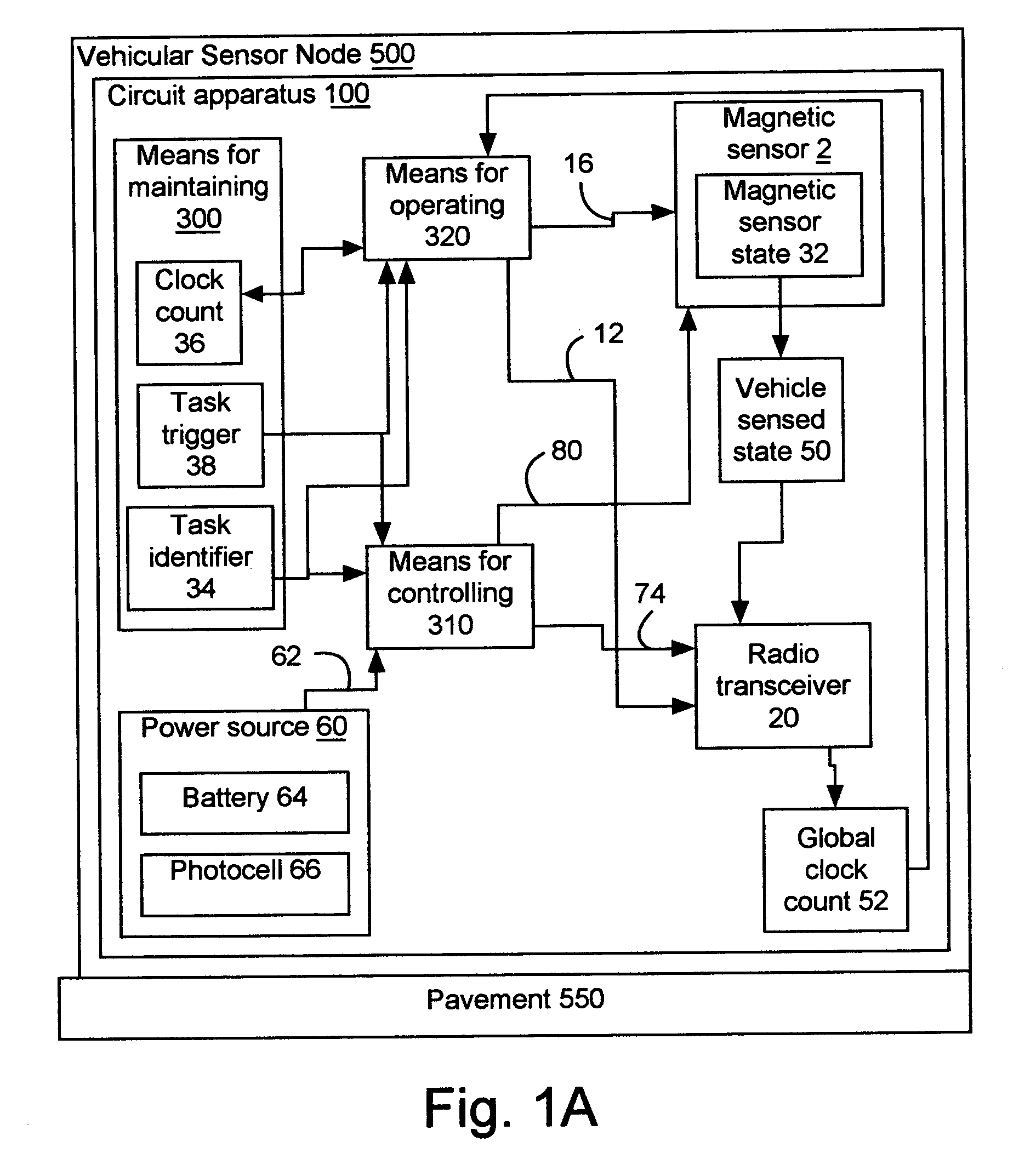
[0029] The invention includes a vehicular sensor node, which is inexpensive, efficient, and reliable. The invention operates as follows: a clock count is maintained to create a task trigger and a task identifier. The power from a power source is controlled for delivery to a radio transceiver and a magnetic sensor based upon the task trigger and the task identifier. The radio transceiver and the magnetic sensor are operated based upon the task identifier, when the task trigger is active. The power source, the radio transceiver, and the magnetic sensor are enclosed in the vehicular sensor node, which is placed upon the pavement and operates for at least five years, and preferably at least ten years, without replacement of the power source or its components.

[0030] The invention as shown FIG. 1A operates as follows: the clock count 36 is maintained to create the task trigger 38 and the task identifier 34. The power 62 from the power source 60 is controlled for delivery to the radio tra...


PUM


Abstract

The invention includes a vehicular sensor node, circuit apparatus and their operations. Power from power source is controlled for delivery to radio transceiver and magnetic sensor, based upon a task trigger and task identifier. The radio transceiver and the magnetic sensor are operated based upon the task identifier, when the task trigger is active. The power source, radio transceiver, magnetic sensor, and circuit apparatus are enclosed in vehicular sensor node, placed upon pavement and operating for at least five years without replacing the power source components. Magnetic sensor preferably uses the magnetic resistive effect to create magnetic sensor state. Radio transceiver preferably implements version of a wireless communications protocol. The circuit apparatus may further include light emitting structure to visibly communicate during installation and/or testing, and second light emitting structure used to visibly communicate with vehicle operators. Making filled shell and vehicular sensor node from circuit apparatus.

Description

CROSS REFERENCES TO RELATED PATENT APPLICATIONS [0001] This application claims priority to Provisional Patent Application Ser. No. 60 / 549,260, filed Mar. 1, 2004 and Provisional Patent Application Ser. No. 60 / 630,366, filed Nov. 23, 2004, both of which are incorporated herein by reference.TECHNICAL FIELD [0002] This invention relates to motor vehicle detection modules, in particular, to self-powered vehicular sensors supporting magnetic sensors in communication with a wireless sensor network, for placement upon pavement. BACKGROUND OF THE INVENTION [0003] Today, there are vehicular sensor nodes using a magnetic sensor based upon a buried inductive loop in the pavement These prior art vehicular sensor nodes have several problems. First, to install them, the pavement must be torn up and the inductive coil buried. This installation process is not only expensive, but the quality of installation depends upon the proficiency of the installer. What is needed is a vehicular sensor node that...

Claims


Application Information

Patent Timeline
IPC IPC(8): G08B21/00G08G1/042
CPCG08G1/042G08G1/14G08G1/141G08G1/145
Inventor KAVALER, ROBERT
Owner SENSYS NETWORKS
Why Eureka
Try Eureka