RF channel calibration for non-linear FM waveforms

Active Publication Date: 2005-09-01
NAVICO HLDG
View PDF4 Cites 22 Cited by
  • Summary
  • Abstract
  • Description
  • Claims
  • Application Information

AI Technical Summary

Benefits of technology

[0005] The present invention is a system, method, and computer program product that performs self-calibration of received pulse-compression radar signals. The system includes an antenna, a receiver, a transmitter, and a radar signal processor. Under normal (non-calibration) operation the radar transmitter generates a pulse compression waveform and transmits it via the antenna. Any reflections from

Problems solved by technology

Phase and amplitude errors in the front end of the system result in degraded system performance by distorting the transmitted and received signals, thereby increasing the range sidelobes after compression.
However, the error budget required for the analog front end is too stringent to guarantee by design over all operating conditi

Method used


Image

  • RF channel calibration for non-linear FM waveforms
  • RF channel calibration for non-linear FM waveforms
  • RF channel calibration for non-linear FM waveforms

Examples


Embodiment Construction

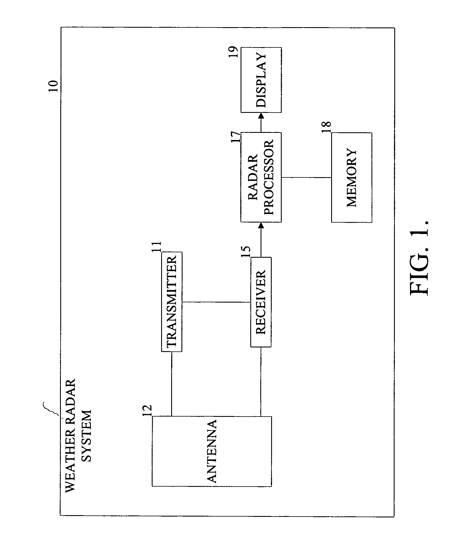
[0012]FIG. 1 illustrates a pulse-compression weather radar system 10 that determines a calibration filter using the actual waveforms produced by the radar system 10 and uses this filter when processing the received pulse compression radar signals. The radar system 10 includes a transmitter 11, an antenna 12, a receiver 15, and a radar processor 17 with memory 18.

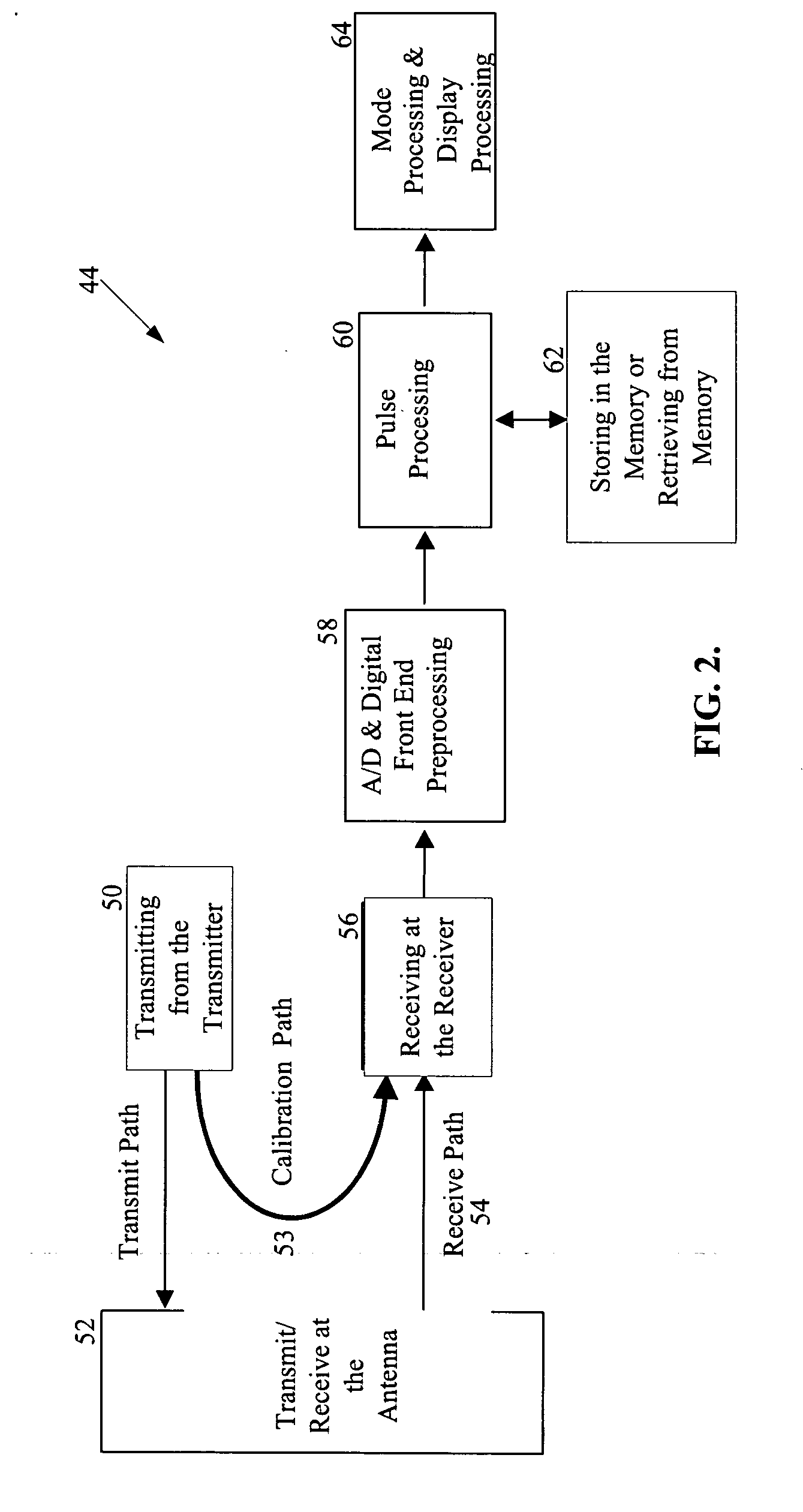
[0013] Referring to FIG. 2, a process 44 performed by the radar system 10 is shown. At steps 50 and 52, the transmitter 11 generally sends pulse-compression waveforms out through the antenna 12. At certain times during a scan, the transmitter 11 instead sends one or more calibration waveforms directly to the receiver 15 via a calibration path 53. At step 56, the receiver 15 detects a signal arriving either from the antenna 12 via a receive path 54, or from the transmitter 11 via the calibration path 53. Both types of signals are sent to the radar processor 17 to undergo analog to digital conversion and front-end preprocessi...


PUM


Abstract

A system, method, and computer program product that performs self-calibration of pulse-compression radar signals. The system includes an antenna, a receiver, a transmitter, and a radar signal processor. Under normal (non-calibration) operation the radar transmitter generates a pulse compression waveform and transmits it via the antenna. Any reflections from this waveform are detected by the same antenna and processed by the receiver. The received radar signal then undergoes pulse compression followed by more mode-specific processing (windshear, weather, ground map, etc.) by the radar processor. During calibration, the radar transmitter generates a similar pulse compression waveform (i.e., calibration pulses), but the calibration pulses bypass the antenna and go directly to the receiver via a “calibration path” built into the hardware. The resulting calibration pulses are used to generate a calibration filter. The calibration filter is applied to the received radar signals in the frequency domain either before or after pulse compression.

Description

FIELD OF THE INVENTION [0001] This invention relates generally to radar and more specifically to weather radar calibration. BACKGROUND OF THE INVENTION [0002] Some Weather Radar systems, such as the Honeywell RDR-4000, transmit pulse compression waveforms whose received signals are pulse compressed during processing. (Some examples of pulse compression waveforms are linear or non-linear FM chirped pulses, Barker codes, etc.) Processing the received data requires that both the transmitted pulse compression waveforms and the received radar signals pass through a system with flat amplitude and linear phase across the bandwidth of the pulse. Phase and amplitude errors in the front end of the system result in degraded system performance by distorting the transmitted and received signals, thereby increasing the range sidelobes after compression. To achieve the required system performance these errors must be held to a fixed level. However, the error budget required for the analog front en...

Claims


Application Information

Patent Timeline
IPC IPC(8): G01S7/40G01S13/28G01S13/95
CPCG01S7/4004G01S13/95G01S13/28Y02A90/10
Inventor HESTER, JEFFREY A.GIDNER, DAWN M.LOGAN, GLORIA M.
Owner NAVICO HLDG
Why Eureka
Try Eureka