Method and allocation device for allocating pending requests for data packet transmission at a number of inputs to a number of outputs of a packet switching device in successive time slots

a packet switching and data packet technology, applied in data switching networks, multiplex communication, digital transmission, etc., can solve the problems of reducing the number of iterations or steps required to achieve an optimized matching solution, and the minimum latency equal to the sum of latencies

Inactive Publication Date: 2005-09-01
IBM CORP
View PDF9 Cites 24 Cited by
  • Summary
  • Abstract
  • Description
  • Claims
  • Application Information

AI Technical Summary

Benefits of technology

[0022] According to one embodiment, the allocation device further comprises one or more intermediate allocation stages which are located between the first allocation stage and the last allocation stage and are connected in series with each other and with the first and the last allocation stage, and for performing a number of intermediate steps of the matching method in successive intermediate time slots between the first time slot and the last time slot. Each of the allocation stages provides intermediate matching information to a su

Problems solved by technology

As line rates continue to increase but cell sizes remain constant, the available arbitration time is shrinking, making it harder to complete enough iterations or steps to achieve an optimized matching solution.
The arbitration in general requires a number of iterations (depending on the number of ports N) that may not be feasible to complete during one

Method used


Image

  • Method and allocation device for allocating pending requests for data packet transmission at a number of inputs to a number of outputs of a packet switching device in successive time slots
  • Method and allocation device for allocating pending requests for data packet transmission at a number of inputs to a number of outputs of a packet switching device in successive time slots
  • Method and allocation device for allocating pending requests for data packet transmission at a number of inputs to a number of outputs of a packet switching device in successive time slots

Examples


Embodiment Construction

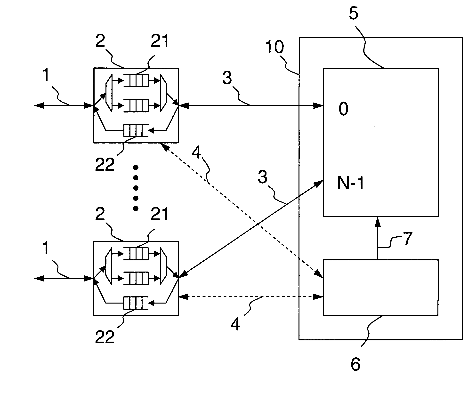
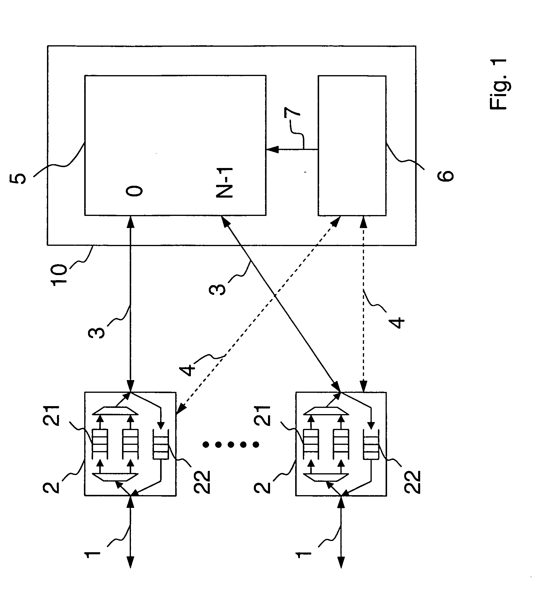
[0039] In FIG. 1 a schematic block diagram of a packet switching device is depicted. The packet switching device comprises N bidirectional full-duplex ingress / egress data links 1 that are connected to N line cards 2. Data packets to be transmitted comprise a payload and header information indicating the requested packet destination and are transmitted and received over the data links 1. Each of the line cards 2 provides one or more data inputs and one or more data outputs and is connected to a switching unit 10 via a bidirectional full-duplex data link 3. The switching unit 10 comprises a routing fabric 5 and an arbitration unit 6. The routing fabric 5, typically a crossbar, comprises N input and N output ports. It can also be possible to provide crossbars having a different number of inputs and outputs.

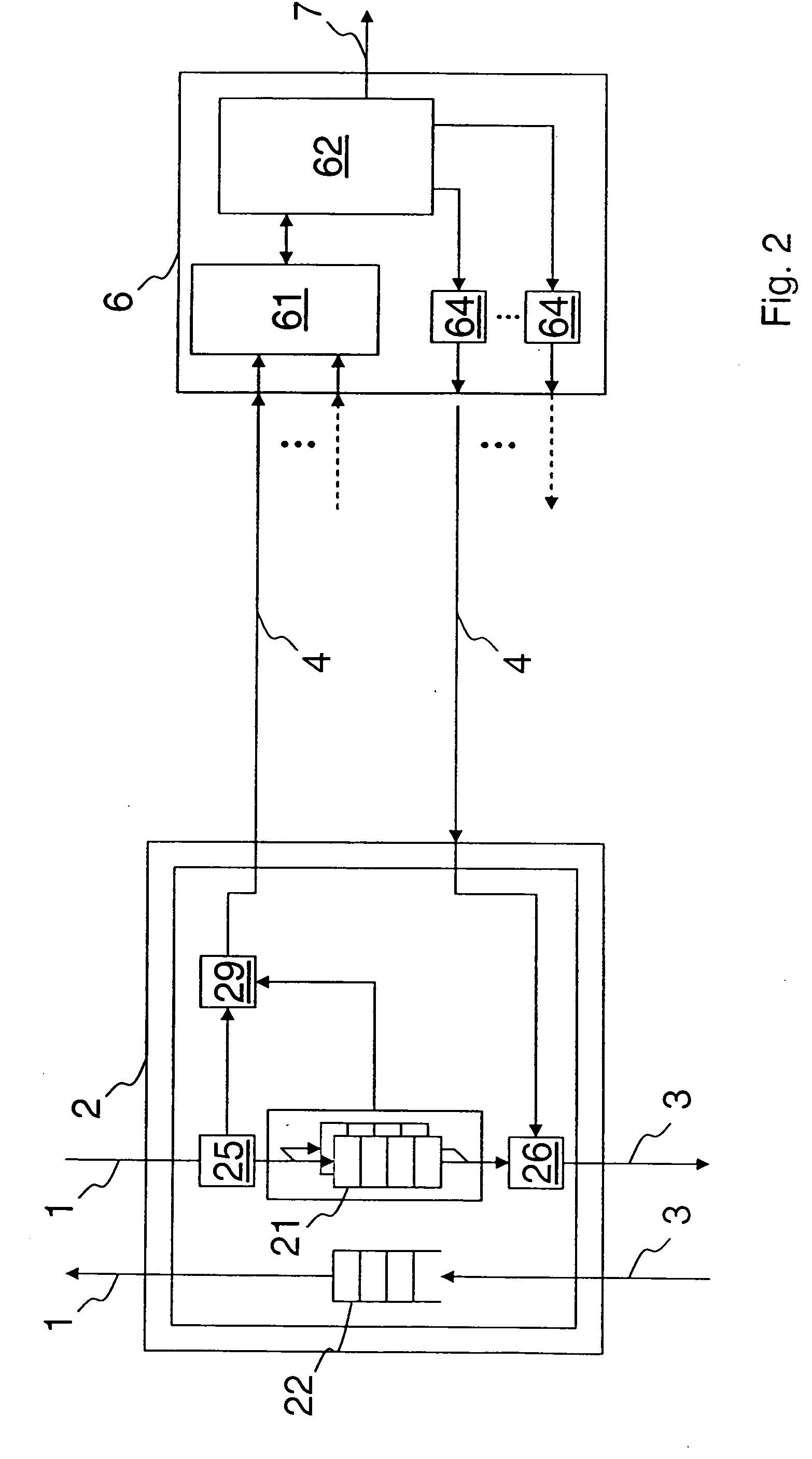
[0040] Each line card 2 is also connected to the arbitration unit 6 with a dedicated bidirectional control link 4, which is used to exchange control messages between the line cards ...


PUM


Abstract

The present invention is related to a method for allocating pending requests for data packet transmission at a number of inputs to a number of outputs of a switching system in successive time slots, wherein according to a matching method the allocation of the pending requests is optimized, wherein the matching method includes a number of steps for incrementally allocating the requests, wherein as a result of each step a matching information is provided, wherein in each time slot a request information is provided, the request information indicating the data packets at the inputs requesting transmission to respective outputs, the matching method comprising the steps of providing a first request information in a first time slot, performing a first step in the first time slot depending on the first request information to obtain a first matching information; providing a last request information in a last time slot successive the first time slot; performing a last step in the last time slot depending on the last request information and depending on the first matching information to obtain a final matching information; and assigning the pending data packets at the number of inputs to the number of outputs in dependence on the final matching information.

Description

[0001] This invention was made with Government support under Subcontract No.: B527064. The Government has certain rights in this invention.FIELD OF THE INVENTION [0002] The present invention relates to the field of packet switching, specifically to the field of crossbar-based packet-switch architectures. BACKGROUND OF THE INVENTION [0003] Many packet switching devices are based on an input-queued architecture, comprising queues sorted per output (virtual output queues—VOQ) at every input line card, a crossbar routing fabric, and a central arbitration unit that computes which input is allowed to send to which output in every time slot. A time slot as herein understood equals the duration of one fixed size packet. [0004] Typically, the arbitration unit is physically located close to the crossbar. In such a system, a data path is provided which comprises the flow of data packets from input line cards through the crossbar to the output line cards, and a control path, which comprises the...

Claims


Application Information

Patent Timeline
IPC IPC(8): H04J3/00H04L12/56
CPCH04L49/101H04L49/3045H04L49/3027H04L49/254
Inventor ABEL, FRANCOISILIADIS, ILIASMINKENBERG, CYRIEL J. A.
Owner IBM CORP
Why Eureka
Try Eureka