System and method for residential emissions trading

a technology of emissions trading and residential homes, applied in non-electric variable control, process and machine control, instruments, etc., can solve the problems of insufficient recognition of residential emission savings, prohibitive transaction costs, and inability to quantify, certify, and transfer the reductions. the effect of energy savings from a simple individual hom

Inactive Publication Date: 2005-09-01
FANNIE MAE +1
View PDF34 Cites 118 Cited by
  • Summary
  • Abstract
  • Description
  • Claims
  • Application Information

AI Technical Summary

Benefits of technology

[0018] Embodiments of the present invention have many potential benefits and advantages. Energy costs are typically the second largest cost for homeowners. A program that provides incentives to invest in energy efficiency will save the homeowner money. It has been estimated, for example, that an efficient house can save 30% on annual energy bills. In addition, embodiments of the present invention may create a valuable new commodity and decrease the cost of energy efficiency. Embodiments of the present invention may reduce the amount of air pollution associated with housing: an energy efficient house may save 2-3 tons of CO2 per year and 3-5 lbs. of NOx per year.

Problems solved by technology

Notably lacking in these schemes, however, are programs for capturing the benefits of potential energy efficiency measures and the resulting emissions reductions by residential consumers.
However, four hurdles have historically kept reductions from residential housing sources off the market: 1.
Residential emission savings are not yet fully recognized by prior known regulatory regimes; 3.
Transaction costs—those associated with quantifying, certifying, marketing, selling, and transferring the reductions—have been prohibitive.
Yet, the energy savings from a simple individual home has a non-measurable impact at electricity generation plants.
Other measures, such as switching to low-VOC paints, paving driveways, and improving home design, can also have significant impacts on air pollution.
Energy costs are typically the second largest cost for homeowners.

Method used


Image

  • System and method for residential emissions trading
  • System and method for residential emissions trading
  • System and method for residential emissions trading

Examples


Embodiment Construction

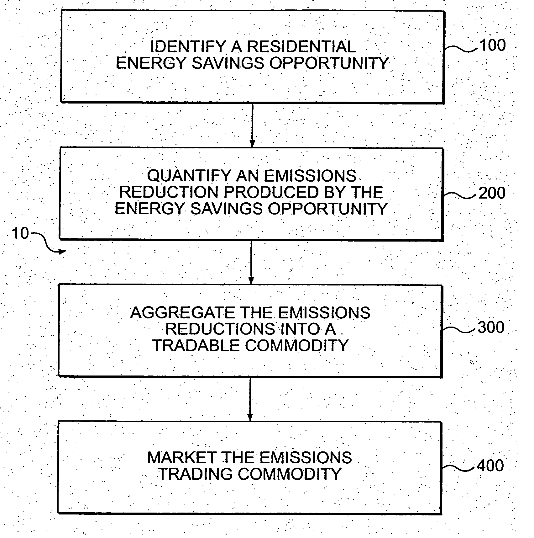
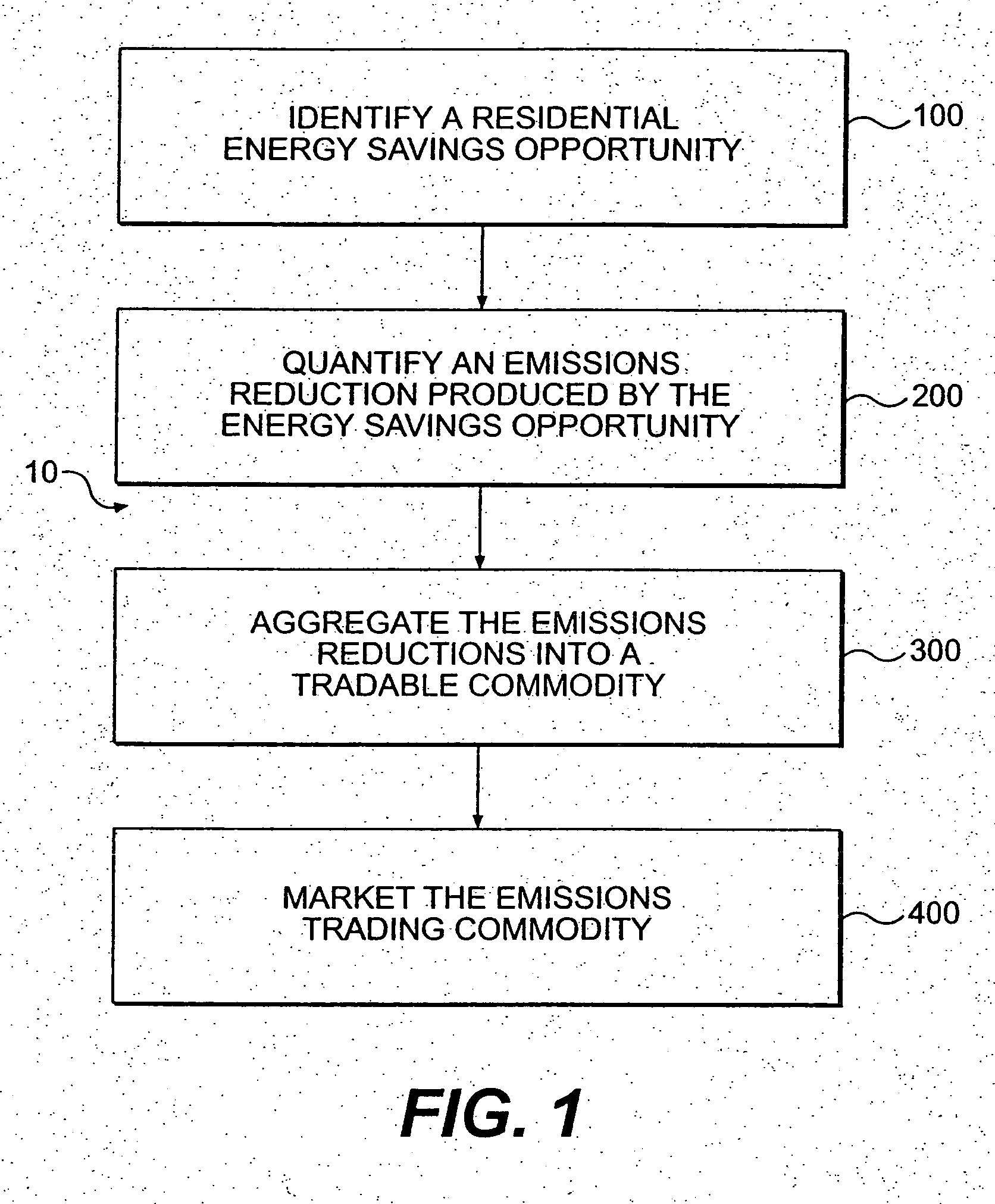
[0049] Reference will now be made to the method of the present invention, an example of which is shown in FIG. 1.

[0050]FIG. 1 is a flow chart depicting an embodiment of the method for identifying, quantifying, and aggregating reductions in residential emissions. As embodied herein, the method 10 comprises the steps of identifying a residential energy savings opportunity 100, quantifying an emissions reduction produced by the energy savings opportunity 200, and aggregating the emissions reductions into a tradable commodity 300, such as, but not limited to, emissions reductions or emissions trading credit(s). The method may further comprise the step of marketing the emissions trading commodity 400.

Identification of Energy Savings Opportunities

[0051] Step 100, identifying a residential energy savings opportunity, may comprise any one or more of a variety of energy efficient improvements. Such improvements may include, but are not limited to: replacing older appliances with more ener...


PUM


Abstract

The present invention is directed to a method of residential emissions trading and a residential emissions trading commodity. In particular, an embodiment of the present invention is a method for identifying, quantifying, and aggregating reductions in residential emissions into a tradable commodity. The step of quantifying the emissions reduction may further comprise the steps of measuring an energy savings resulting from the energy savings opportunity and calculating the emissions reduction resulting from the energy savings. The method may further comprise the steps of verifying the quantification of the emissions reduction and monitoring the residential energy savings opportunities and the quantification of the emissions reduction.

Description

CROSS REFERENCE TO RELATED APPLICATIONS [0001] This application is a continuation of U.S. patent application Ser. No. 10 / 290,753, filed Nov. 8, 2002, which claims the benefit under 35 U.S.C. § 119(e) of U.S. Provisional Application No. 60 / 342,853, filed Dec. 28, 2001, both entitled “System and Method for Residential Emissions Trading.” The entire contents of these applications are hereby incorporated by reference.FIELD OF THE INVENTION [0002] The present invention relates to a method of residential emissions trading and a residential emissions trading commodity. In particular, the present invention is directed to a method of identifying, quantifying, and aggregating reductions in residential emissions into a form in which they can be traded for consideration. The present invention further comprises a method for measuring, monitoring, and verifying residential energy savings and the resulting emissions reductions. Energy savings are quantified and aggregated to produce a commodity th...

Claims


Application Information

Patent Timeline
Patent Type & Authority Applications(United States)
IPC IPC(8): G06Q30/00H02J3/00
CPCG06Q30/02G06Q50/06G06Q90/00H02J3/008Y02E40/76Y04S50/10Y04S10/545Y04S10/58Y04S50/14Y02E40/70Y04S10/50
Inventor RAINES, FRANKLIN D.SAHADI, ROBERT J.BERLIN, KENNETHDESIDERIO, MICHELLELESMES, SCOTTCAVEY, ELIZABETH ARNERBARTELS, CARLTONBARTELS, JANE
Owner FANNIE MAE
Why Eureka
Try Eureka