Panel-type subfloor assembly for anchored/resilient floor

a subfloor and panel-type technology, applied in the direction of resiliently mounted floors, flooring, ceilings, etc., can solve the problems of difficult simultaneous achievement, adversely affecting the performance uniformity of the floor, and the floorboards to the base, so as to improve the resistance to lateral movement, the degree of structural integrity, and the effect of reducing the risk of lateral movemen

Inactive Publication Date: 2005-09-08
ROBBINS INC
View PDF15 Cites 33 Cited by
  • Summary
  • Abstract
  • Description
  • Claims
  • Application Information

AI Technical Summary

Benefits of technology

[0008] This panel-type subfloor provides a degree of structural integrity for the floor by holding the panels along two opposite ends of each of the slots. The hold-down forces are stronger than other panel-type floors held along only one edge. Also, the cooperative interaction between the slots and fasteners, including the size, shape and use of one pin per channel, gives the floor a “self-alignment” capability. This means that the fasteners are able, to some extent, to reorient themselves in response to lateral sheer forces, forces that inevitably occur with all installed floors. However, this reorientation, or self-alignment, does not adversely impact the hold-down capability of the pins or the resilience of the floor.
[0009] Stated another way, another primary benefit of the present invention is the floor's greater tolerance to lateral movement. In one respect, the vertical sidewalls of the fasteners may flex to absorb lateral torsion forces. Thus, the invention accommodates greater downward and lateral forces, while imparting less stress to the fastening structure. The present invention also requires less shimming than several commercially available anchored / resilient panel-type floors.
[0010] Also, the use of elongated fasteners within elongated slots, with one pin per channel, simplifies installation and reduces the total number of floor components. For example, the total number of anchor pins and the labor costs associated with installing the anchor pins are significantly reduced.
[0011] Most of the components of the floor according to this invention are standard and readily available. For instance, the panels may be made of standard plywood, even in lengths of up to eight feet or longer. The longer the subfloor panels, the easier and more expedient the installation, resulting in lower labor costs. The invention is particularly advantageous when the upper wear layer comprises standard parallel rows of end-to-end floorboards, but the invention could also be used with other floor surfaces.
[0014] If one or more of the panels has more than one slot, preferably the ends of the slots for any given panel will not be contiguous along the longitudinal direction of the floorboards. Alternatively or additionally, it may be desirable to transversely space the panels. Also if desired, an elongated slot may comprise two open-ended slot portions of adjacently located panels. With this structure, the elongated fastener spans between and secures two panels, thereby helping to assure continuity and uniform resiliency. According to another preferred embodiment of the invention, the elongated slots may be oriented parallel, or in alignment with, the longitudinal direction of the panels. This structure would simplify installation.
[0016] Compared to prior anchored / resilient floors, and particularly panel-type anchored / resilient floors, the floor of this invention achieves high stability and strength, but with significantly less material and at lower cost. When the floorboards are secured to the subfloor panels with the nailing strips secured to the lower panel, the combined structure has a cross-lamination effect, particularly if the panels are oriented at an oblique angle. Where desired, the structure may have a height profile of under about two inches. Thus, the invention achieves a high strength floor with a relatively low material cost.

Problems solved by technology

This moisture-caused expansion and contraction of floorboards adversely affects the performance uniformity of the floor.
These dual objectives, to resiliently support the floorboards above the base and to anchor the floorboards to the base, are not easy to simultaneously achieve.

Method used


Image

  • Panel-type subfloor assembly for anchored/resilient floor
  • Panel-type subfloor assembly for anchored/resilient floor
  • Panel-type subfloor assembly for anchored/resilient floor

Examples


Embodiment Construction

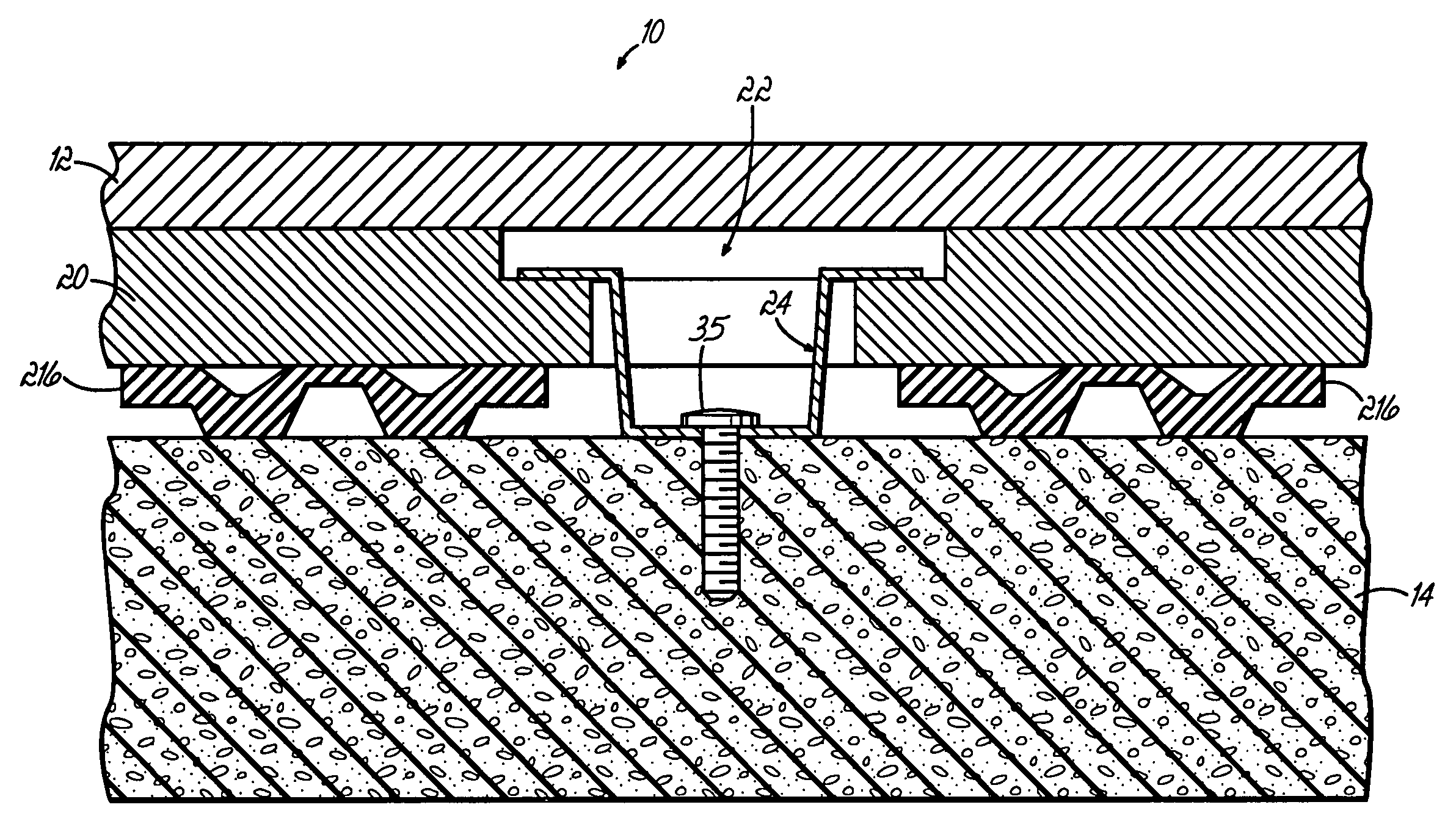
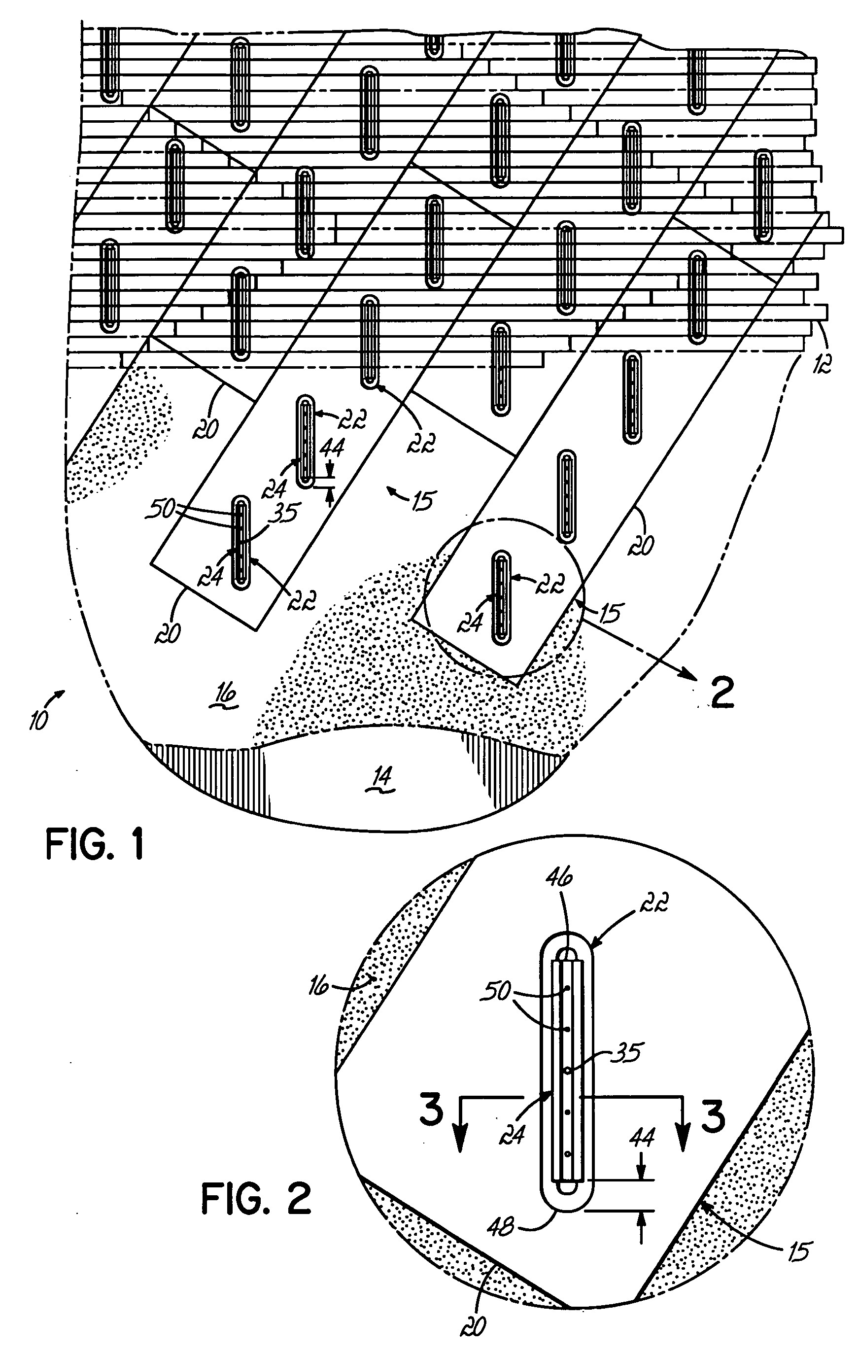
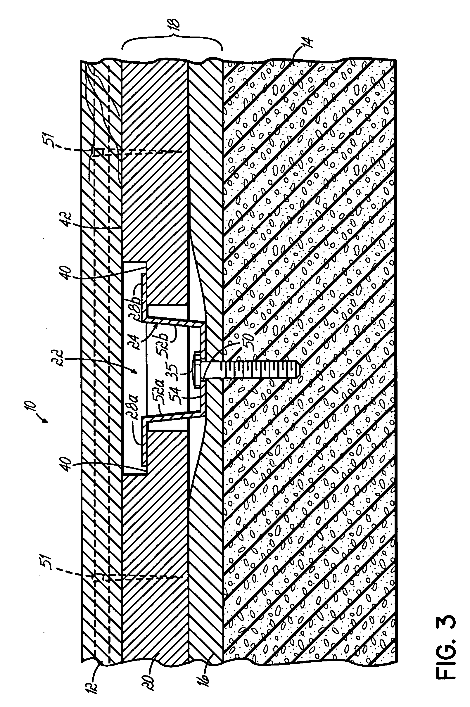
[0026]FIG. 1 shows a plan view of a floor 10 constructed in accordance with a first preferred embodiment of the invention. The floor 10 includes an upper wear layer 12, which may be tongue and groove floorboards extending end-to-end in parallel rows across a lower base 14. In FIG. 1, the view is along the length of the floor, i.e. from one basket toward the other. A subfloor layer 15 comprising a plurality of panels 20 resides below the wear layer 12. The panels 20 are also arranged end-to-end in parallel rows. However, the rows of panels 20 are oriented along an axis that resides at an angle of about 60° relative to the floorboards of the wear layer 12. The wear layer 12 is supported in spaced relation above the base 14, with a spacer layer 16 and the subfloor layer 15 residing therebetween. In FIGS. 1 and 2, the spacer layer 16 comprises a compressible panel-like pad or carpet.

[0027] In one sense, each of the panels 20 is essentially a part of a subfloor assembly 15 that includes...


PUM


Abstract

A panel-type subfloor assembly for an anchored / resilient floor includes a plurality of elongated panels laid end-to-end in parallel rows along a first direction, the panels having elongated slots formed therein that are oriented at an oblique angle relative to the first direction. For the entire floor, this results in a plurality of aligned rows of elongated slots oriented at an oblique angle relative to the first direction. Each slot cooperates with an elongated fastener, namely an elongated dual flanged channel held by at least one pin. The fastener is positioned within the respective slot and adapted to hold the respective panel to the base along two longitudinal edges of the slots, in a manner that limits upward movement of the panel while permitting downward deflection. The slots are longitudinally and transversely oversized relative to the flanges of the fastener, and preferably each fastener is secured to the base via only a single pin. This promotes self-alignment of fasteners and the floor in response to lateral sheer forces, thereby resulting in floor with a high degree of structural integrity that is able to withstand substantial lateral sheer forces and / or vertically directed forces. An upper wear layer is secured to the panel-type subfloor. Compared to other panel-type anchored / resilient floors, the floor of this invention simplifies and reduces installation and handling time, resulting in reduced labor costs. The structure itself also provides high strength and durability, but with reduced quantity and cost of materials.

Description

CROSS-REFERENCE TO RELATED APPLICATIONS [0001] This application is a continuation of U.S. patent application Ser. No. 10 / 447,903 filed on May 29, 2003 by Michael W. Niese et al., which application is incorporated herein in its entirey.FIELD OF THE INVENTION [0002] The present invention relates to hardwood floors, and more particularly to an anchored / resilient floor with a panel-type subfloor that provides strong structural integrity and reduces susceptibility to lateral sheer forces. BACKGROUND OF THE INVENTION [0003] Wood floors remain popular for athletic facilities, particularly for basketball floors. In a typical hardwood floor, a wear layer of floorboards resides over a base, with a subfloor residing below the wear layer and above the base, and resilient pads residing between the subfloor and the base. The pads create space between the floor and the base, thereby minimizing moisture ontake by the subfloor or the floorboards, which are usually made of wood. The pads also provide...

Claims


Application Information

Patent Timeline
Patent Type & Authority Applications(United States)
IPC IPC(8): E04F15/04E04F15/22
CPCE04F15/04E04F2201/0517E04F15/225E04F15/02194E04F2015/0205E04F2015/02055E04F15/22
Inventor NIESE, MICHAEL W.ELLIOT, PAUL W.PUENING, JOHN RICHARD
Owner ROBBINS INC
Why Eureka
Try Eureka