Pressure sensor
- Summary
- Abstract
- Description
- Claims
- Application Information
AI Technical Summary
Benefits of technology
Problems solved by technology
Method used
Image

Examples
first embodiment
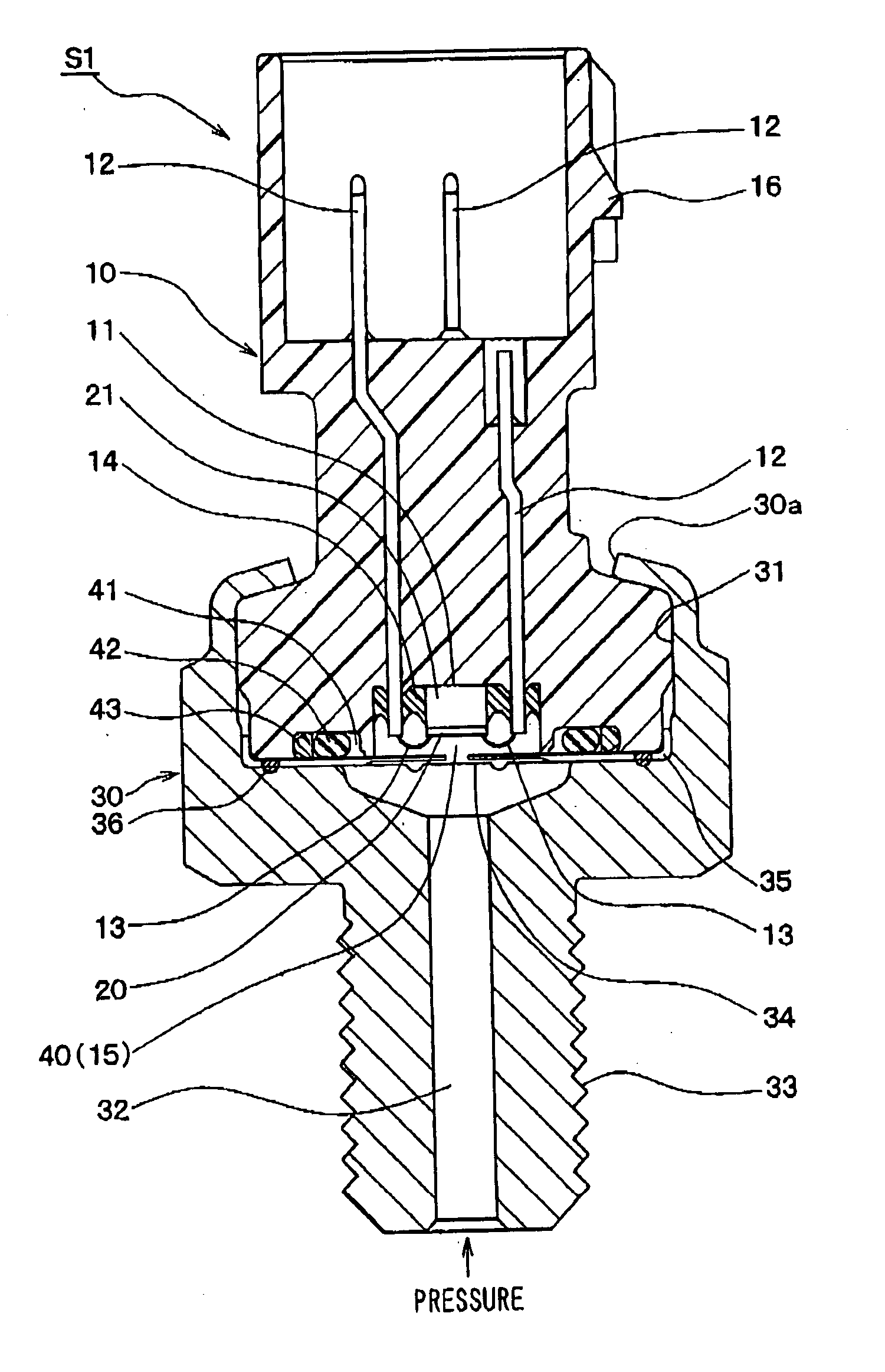
[0023] A pressure sensor S1 is shown in FIG. 1. The pressure sensor S1 is installed in a vehicle and used for detecting pressure levels of air conditioner coolant or fuel injection pressure.
[0024] The pressure sensor S1 has a connector case 10 and a case 30 integrated in one unit. The connector case 10 is a first case and the case 30 is a second case. The connector case 10 is made of resin, such as polyphenylene sulfide (PPS) or polybutylene terephthalate (PBT). It formed substantially in a cylinder. A recess 11 is formed in the connector case 10 at the first end of the connector case 10, which is a lower end in FIG. 1.
[0025] A sensor chip 20, which is a pressure sensing element, is arranged in the recess 11. The sensor chip 20 is a diaphragm type semiconductor sensor chip having a diaphragm (not shown) as a pressure receiving surface and converts pressure received by the diaphragm to electrical signals. Then, it outputs the electrical signals as sensor signals. The sensor chip 20...
second embodiment
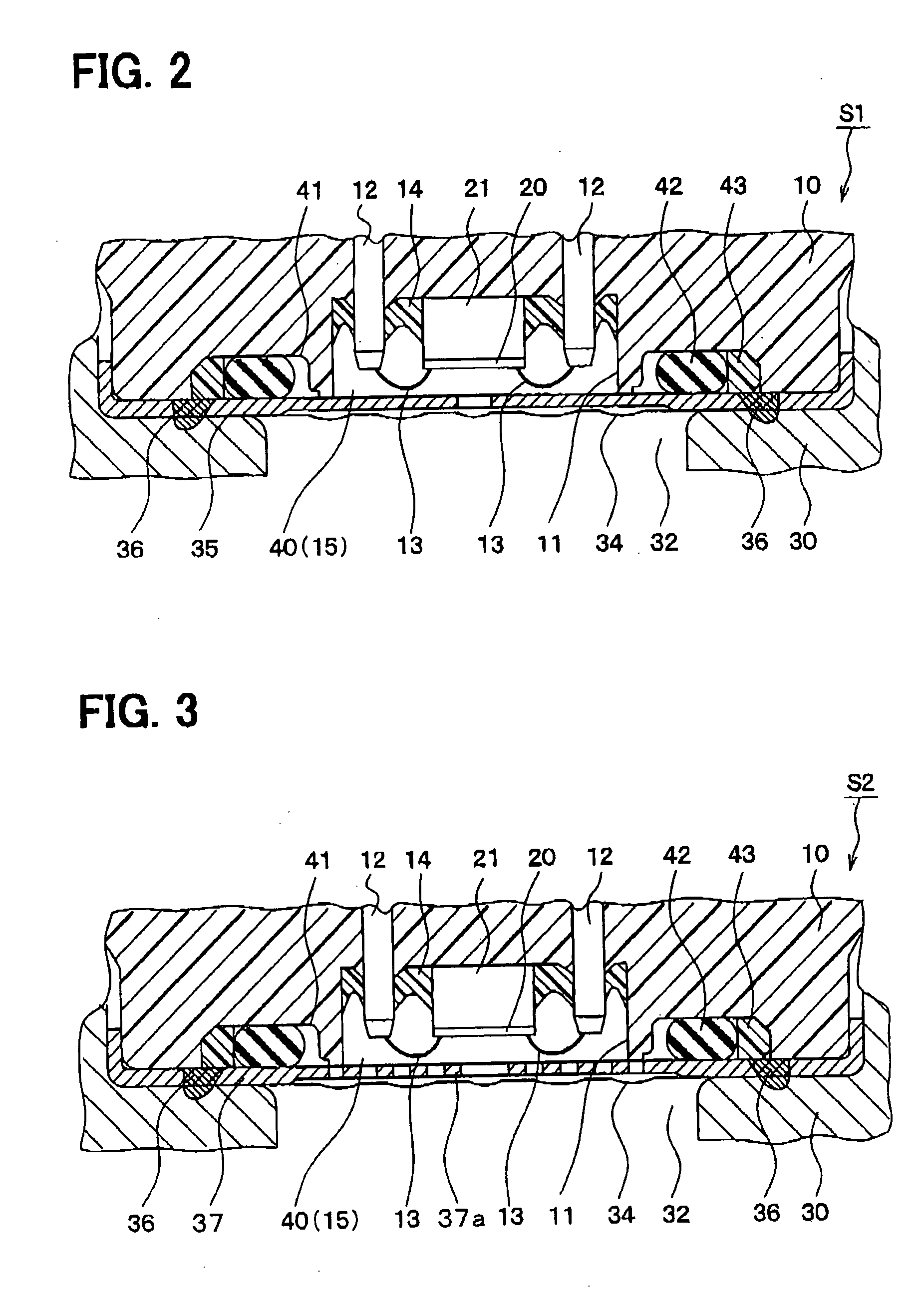
[0049] An enlarged view of a pressure sensor S2 around the pressure sensing chamber 40 is shown in FIG. 3. Configurations of the pressure sensor S2 that are different from the pressure sensor S1 will be discussed.
[0050] A mesh screen 35a is attached to the welding ring 37 to cover the hole. This type of welding ring 37 can be also easily produced by stamping or etching. The area of the welding ring 37 with the mesh screen 37a is placed in the pressure sensing chamber 40 between the sensor chip 20, the wires 13, and the diaphragm 34. Namely the inner portion of the welding ring 37 is placed in the chamber 40 between the sensor chip 20, the wires 13, and the diaphragm 34.
[0051] With this configuration, the diaphragm 34 touches the mesh screen 35a when the diaphragm 34 moves toward the sensor chip side. As a result, the movement of the diaphragm 34 is restricted. Namely, excessive movement of the diaphragm 34 is reduced. The diaphragm 34, the sensor chip 20, and the wires 13 are less...
third embodiment
[0052] An enlarged view of a pressure sensor S3 around the pressure sensing chamber 40 is shown in FIG. 4. Configurations of the pressure sensor S3 that are different from the pressure sensors S1, S2 embodiment will be discussed.
[0053] The welding ring 38 does not have the inner portion that covers the pressure sensing chamber 40 as the welding rings 35 and 37 of the pressure sensors S1, S2 do. An insulator film 50 having electrical insulation is formed on a surface of the diaphragm 34 on the pressure sensing chamber side. The insulator film 50 can be any type of film as long as it is properly formed on the diaphragm 34 and stays on the diaphragm 34 even when the diaphragm 34 is deformed for instance, an insulator material, such as parylene, is evaporated onto the diaphragm 34.
[0054] Electrical shortage among the diaphragm 34, the sensor chip 20, and the wires 13 is less likely to be produced because the diaphragm 34 is electrically insulated from the sensor chip 20 and the wires ...
PUM
 Abstract
Description
Claims
Application Information
 - R&D Engineer
- R&D Manager
- IP Professional
- Industry Leading Data Capabilities
- Powerful AI technology
- Patent DNA Extraction
Browse by: Latest US Patents, China's latest patents, Technical Efficacy Thesaurus, Application Domain, Technology Topic.
© 2024 PatSnap. All rights reserved.Legal|Privacy policy|Modern Slavery Act Transparency Statement|Sitemap