
Dynamic legged robot

a robot and dynamic technology, applied in the field of legged robots, can solve the problems of large amount of computation, large range of mobility of the robot that must be tethered to a power supply, and relatively slow movemen

Inactive Publication Date: 2005-09-08
RGT UNIV OF CALIFORNIA
View PDF4 Cites 32 Cited by
  • Summary
  • Abstract
  • Description
  • Claims
  • Application Information

AI Technical Summary

Benefits of technology

[0016] f) Connections between actuator and robot structure that allow energy recovery during each gait cycle.
[001

Problems solved by technology

These robots move relatively slowly, and a large amount of computation is required to for leg placement over uneven terrain.
However, one of the limiting factors of these robots, is that they must be plugged into the wall with a tether to a power source.
A robot that must be tethered to a power supply is significantly limited in its range of mobility.
Other robots, such as described by Paynter in U.S. Pat. No. 5,040,626 (1991), move in a quasi-static fashion and have gaits where multiple legs are in contact with the ground at all times; thereby limiting the speed of the robot.
Therefore, these gaits require continual reversal of angular momentum of each leg, which reduces the top speed of the robot.

Method used


Image

  • Dynamic legged robot
  • Dynamic legged robot
  • Dynamic legged robot

Examples


Embodiment Construction

[0032] A robot is a machine that includes the following components: structure, actuator, power source, sensor, and controller. A mobile robot is a robot that can travel from one location to another. The machines described herein are a class of mobile robots that use legs for locomotion. The following sections describe the various robot components that comprise the invention of a dynamic legged robot.

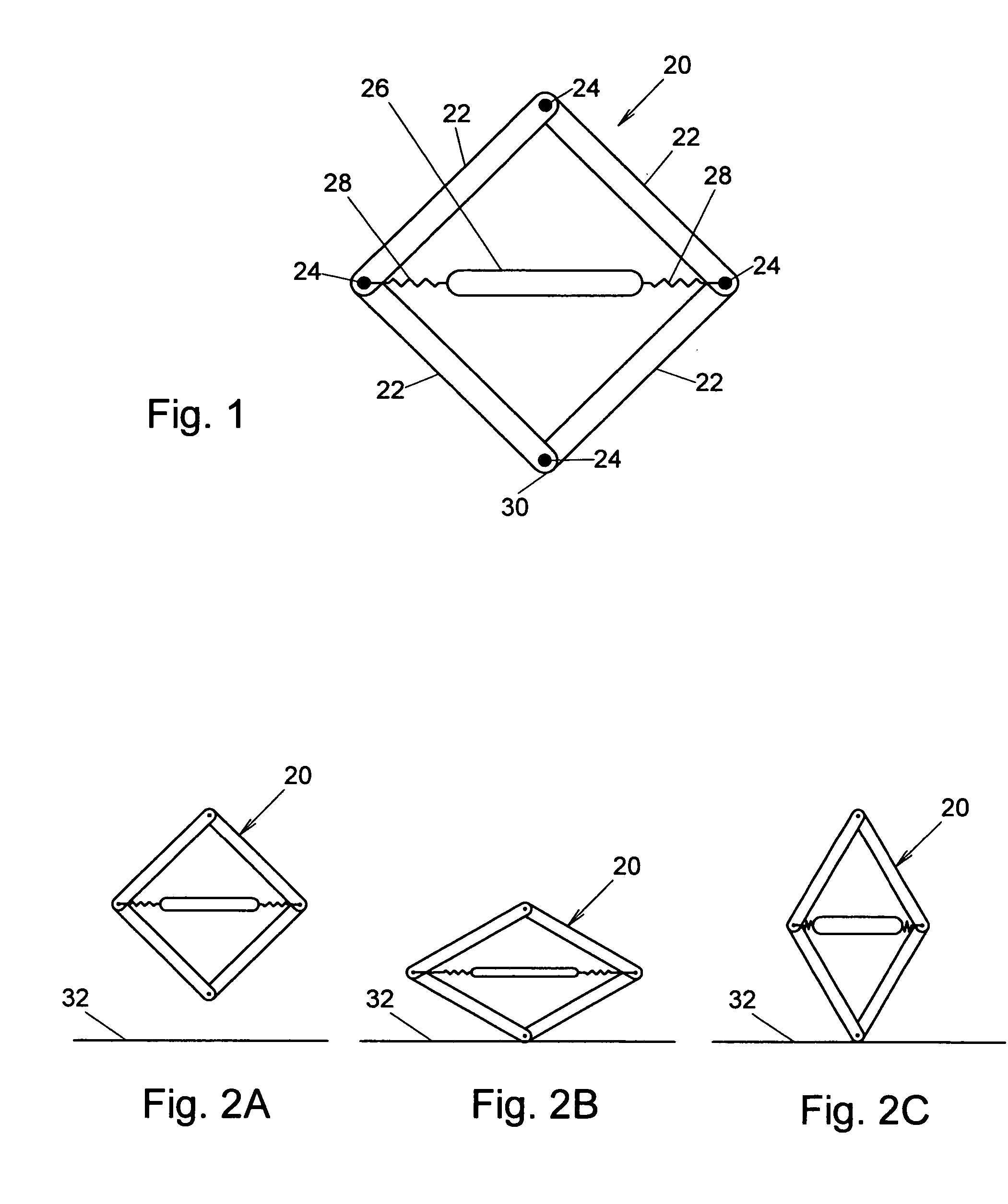
FIGS. 1 and 2A-2C—Embodiment of Robot Structure

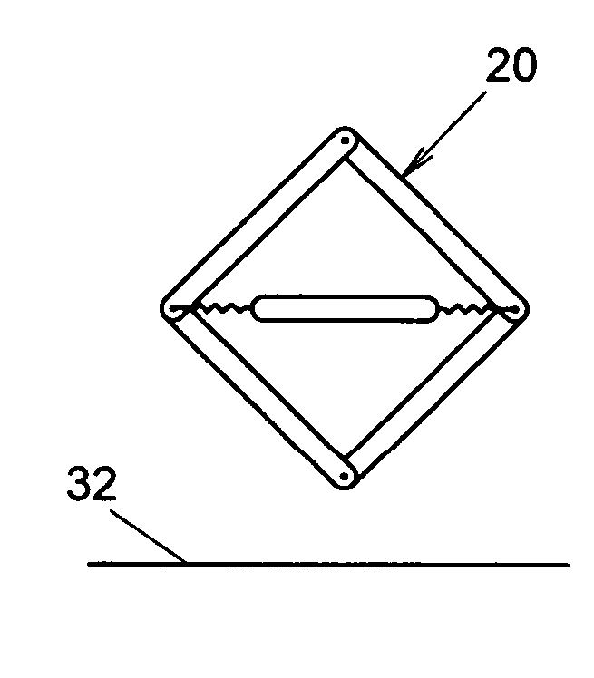
[0033] A preferred embodiment of the robot structure 20 of the present invention is shown in FIG. 1. A robot structure is the primary mechanical structure that provides support for a robot's actuators, sensors, power sources, appendages, and other components. The robot structure 20 is a Closed Kinematic Chain, consisting of links 22 and pivots 24. In this embodiment there are four links 22 connected by four pivots 24. An actuator 26 is connected through springs 28 to the robot structure 20. The actuator 26 contracts when activated and ther...


PUM


Abstract

A legged robot having a robot structure (20) in the form of a closed kinematic chain and an actuator (26) that contracts when activated. The contraction of the actuator extends a foot element (30) such that it can excerpt a pushing force against a ground surface. When the foot element excerpts sufficient force the legged robot can separate from the ground surface and achieve a dynamic hopping motion.

Description

CROSS-REFERENCE TO RELATED APPLICATIONS [0001] Provisional Patent Application No. 60 / 548,362 filed Feb. 27, 2004.BACKGROUND—FIELD OF INVENTION [0002] This invention relates to mobile robots, specifically to legged robots. BACKGROUND—DESCRIPTION OF PRIOR ART [0003] The goal of developing a walking machine has been pursued since the late 1800s. One objective has been mobility, since the large majority of land is not reachable by wheeled and tracked vehicles. Other objectives include a greater understanding of biological systems and the design of human prostheses. And finally entertainment has always been a component of walking machine design. [0004] Since the 1960s a number of successful walking machines have been built. A majority of these machines have four or more legs, and move in a quasi-static fashion meaning that at least three legs are kept on the ground at one time with the center of gravity of the robot kept within the region defined by the grounded feet. These robots move r...

Claims


Application Information

Patent Timeline
IPC IPC(8): B62D51/06
CPCB62D57/02
Inventor DELSON, NATHAN J.
Owner RGT UNIV OF CALIFORNIA
Learn More