Method and apparatus for object based visibility culling

a technology of object-based visibility and culling, applied in the field of graphics processing, can solve problems such as difficult culling decisions, inefficiency based on the rendering of graphic elements, pixels,

Inactive Publication Date: 2005-09-08
ATI TECH INC
View PDF29 Cites 36 Cited by
  • Summary
  • Abstract
  • Description
  • Claims
  • Application Information

AI Technical Summary

Problems solved by technology

In a typical graphics processing system, inefficiencies arise based on the rendering of graphic elements, such as pixels, which are not visible to an end user.
Typically, the CPU is unable to detect a divider with an object behind it relative to the defined viewing po...

Method used


Image

  • Method and apparatus for object based visibility culling
  • Method and apparatus for object based visibility culling
  • Method and apparatus for object based visibility culling

Examples


Embodiment Construction

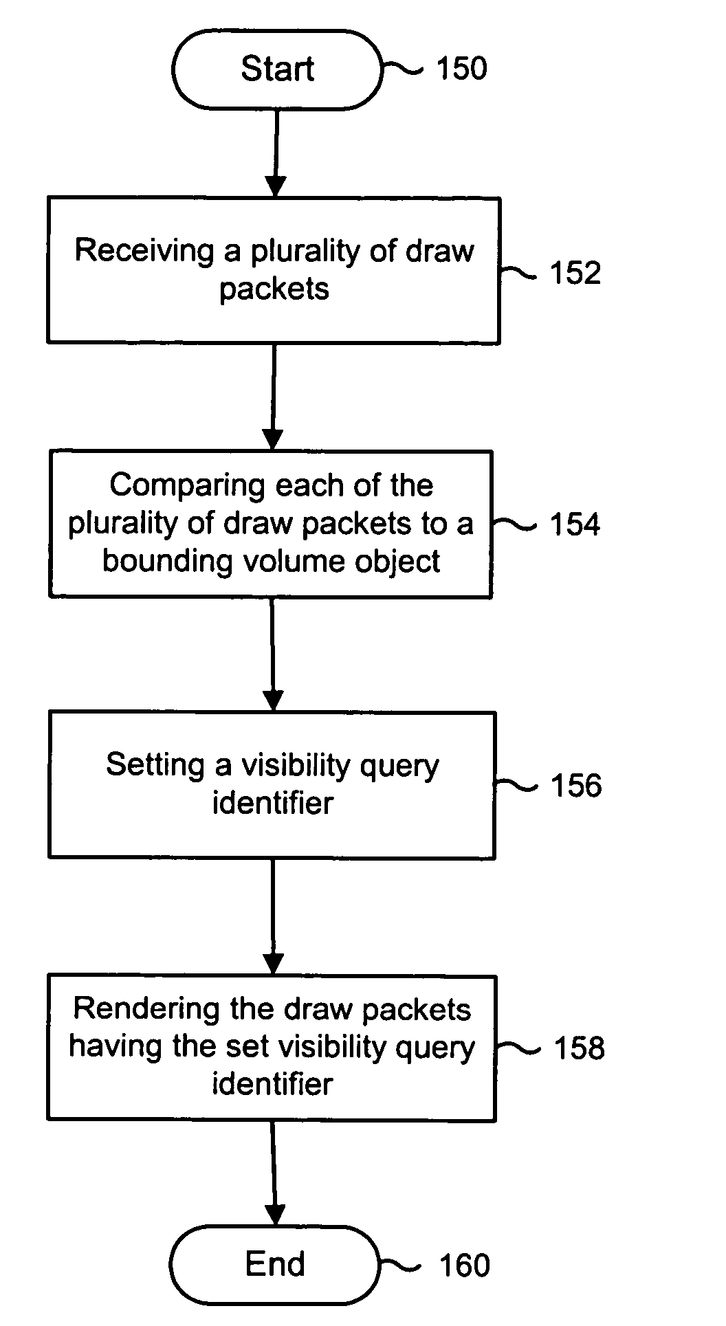
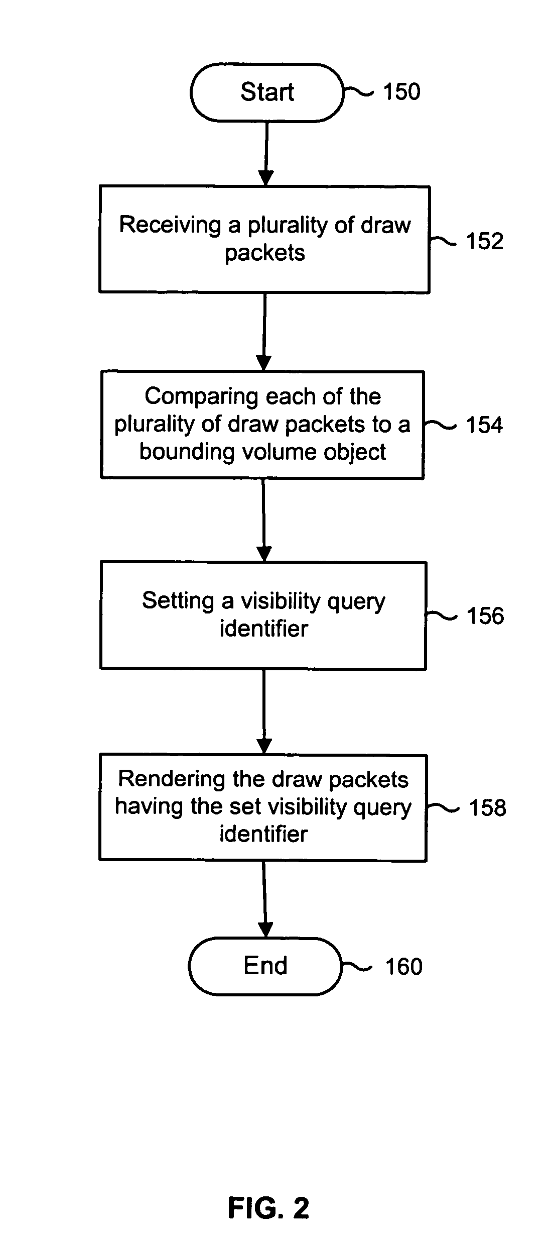
[0011] Generally, the present invention includes the method and apparatus for object-based visibility culling, including the steps of receiving a plurality of draw packets. As discussed above, a draw packet may be a plurality of rendering elements, such as pixels, vertices, or any other suitable rendering element as recognized by one having ordinary skill in the art. The method and apparatus further includes comparing each of the plurality of draw packets to a bounding volume object, wherein the bounding volume object may be a low resolution geometric representation of a specific object, such as a window, doorway, or any other suitable portal through which viewing definitions may be defined. Whereupon, for each of the plurality of draw packets, if the draw packet is deemed potentially visible, setting a visibility query identifier and rendering the draw packets having the set visibility query identifier. In one embodiment, the visibility query identifier may be a single or multi bit...


PUM


Abstract

A method and apparatus for object-based visibility culling includes receiving a plurality of draw packets, such as pixels or vertices. The method and apparatus further includes comparing each of the plurality of draw packets to a bounding volume object, wherein the bounding volume object may be a low resolution geometric representation of a specific object. Whereupon, for each of the plurality of draw packets, if the draw packet is deemed potentially visible, setting a visibility query identifier and rendering the draw packets having the set visibility query identifier.

Description

FIELD OF THE INVENTION [0001] The present invention relates to graphics processing and more specifically to the removal of non-visible render objects prior to rendering. BACKGROUND OF THE INVENTION [0002] In a typical graphics processing system, inefficiencies arise based on the rendering of graphic elements, such as pixels, which are not visible to an end user. As the resolution of a graphical display increases, the amount of specific graphics rendering also thereby increases. Therefore, to reduce the amount of processing overhead there exist techniques for eliminating rendering elements prior to being processed by a graphics processing pipeline. [0003] For example, one technique is the operation of a hierarchical Z buffering technique whereupon a rendering element is compared in a depth test relative to other rendering elements within a display screen. Another operating technique is the determination if a rendering element falls within a view frustum such that it would be visible ...

Claims


Application Information

Patent Timeline
IPC IPC(8): G06T15/40
CPCG06T15/40
Inventor MITCHELL, JASON L.MOREIN, STEPHEN L.TAYLOR, RALPH C.CAREY, JOHN
Owner ATI TECH INC
Why Eureka
Try Eureka