Connector

a technology of connecting rods and connectors, applied in the direction of coupling device connection, securing/insulating coupling contact members, electrical devices, etc., can solve the problems of terminal member falling out, reducing the size of the connection, and not being able to ensure, so as to reduce the size and reliably prevent the terminal member from falling out

Active Publication Date: 2005-09-08
KK TOKAI RIKA DENKI SEISAKUSHO
View PDF5 Cites 6 Cited by
  • Summary
  • Abstract
  • Description
  • Claims
  • Application Information

AI Technical Summary

Benefits of technology

[0020] A connector relating to the present embodiment as described above provides an excellent effect in that it is possible to reduce size while maintaining a function of reliably preventing a terminal member from falling out from a terminal hole.

Problems solved by technology

Thus, restoring force may not be sufficient and it may not be possible to ensure an amount of engagement with the engaging portion.
An inadequate engaging amount may result in the terminal member falling out from the terminal hole in accordance with connections of the terminal member to other terminal members.
However, with a connector featuring the housing lance structure as described above, it is not possible to reduce thickness of the plate spring piece, because strength of the plate spring piece must be maintained.
That is, it is not possible to reduce space in the terminal hole 52 that is occupied by the plate spring piece, including space that is occupied by the plate spring piece in the deformed position (a lance space for engaging the terminal member with the engaging pawl).
Therefore, structure of a mold at a time of molding, that is, a die drawing structure, is complicated, and reductions in size are even more difficult in regard to maintaining strength and spacing of the mold (and of insert pieces thereof).

Method used


Image

  • Connector
  • Connector
  • Connector

Examples


Embodiment Construction

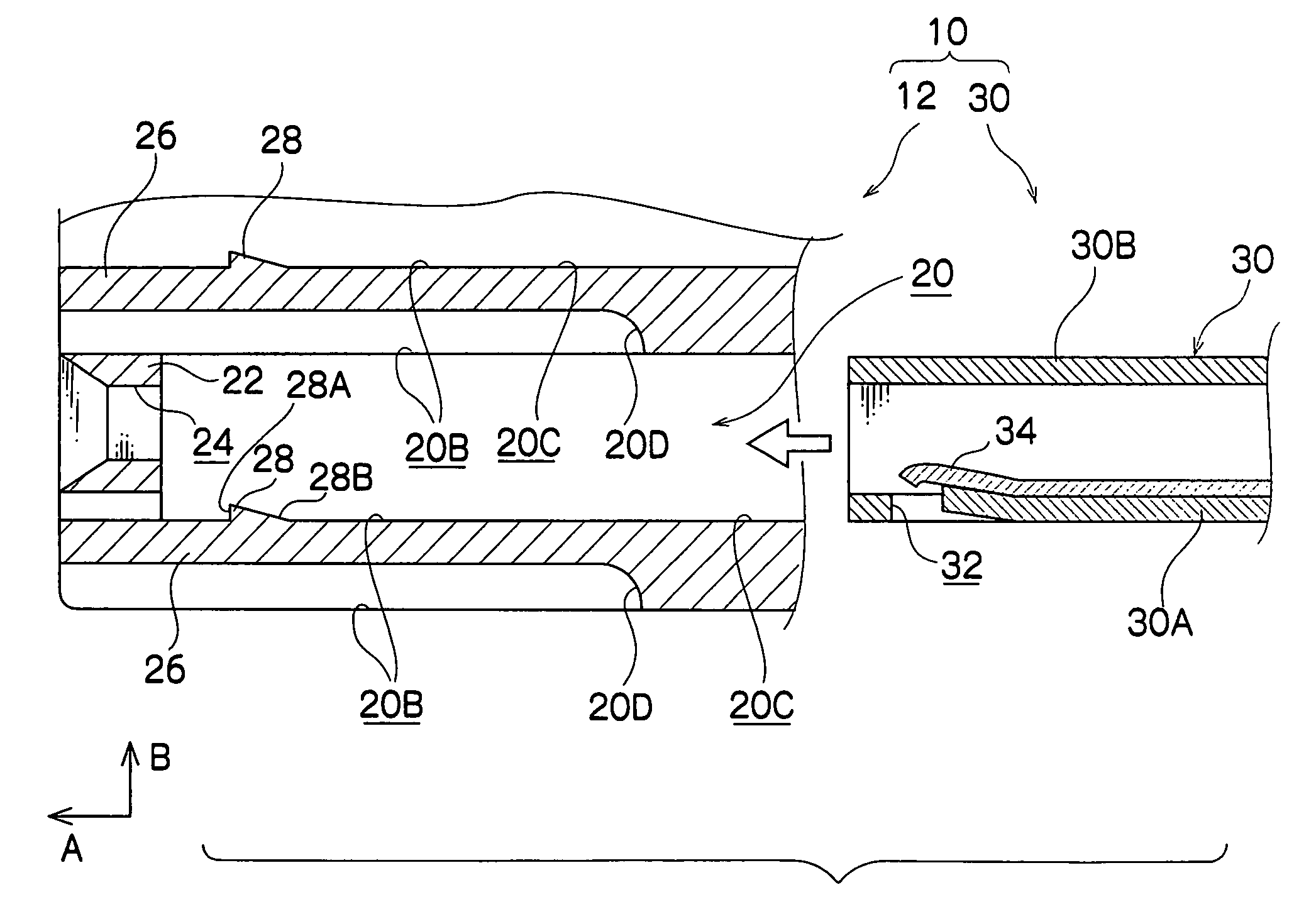
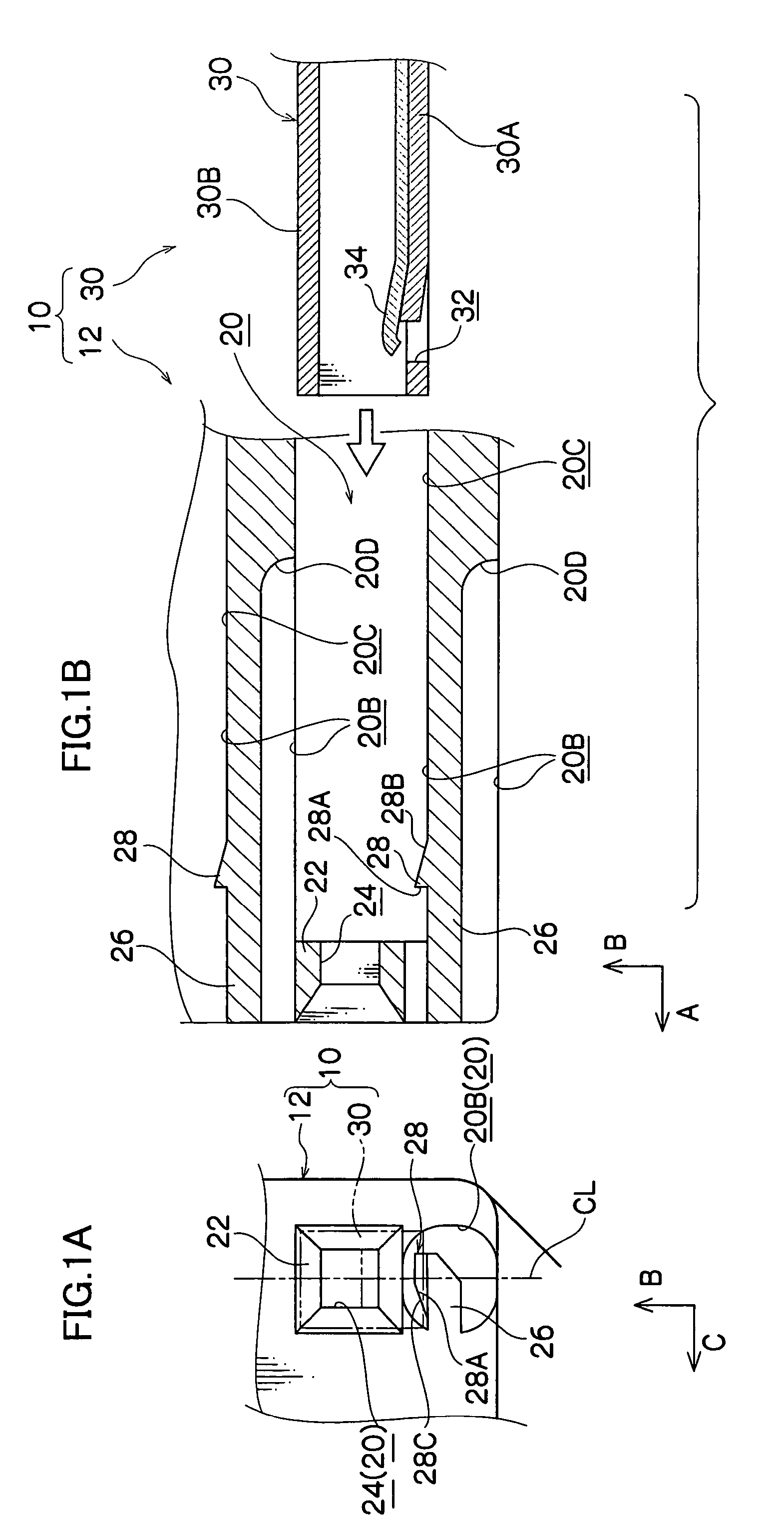
[0028] A connector 10 relating to an embodiment of the present invention will be described with reference to FIGS. 1 to 4. For the sake of convenience, in the following descriptions, a direction shown by an arrow A where appropriate in the drawings is referred to as forward, and directions shown by an arrow B and an arrow C, which intersect arrow A, are referred to as upward and rightward, respectively.

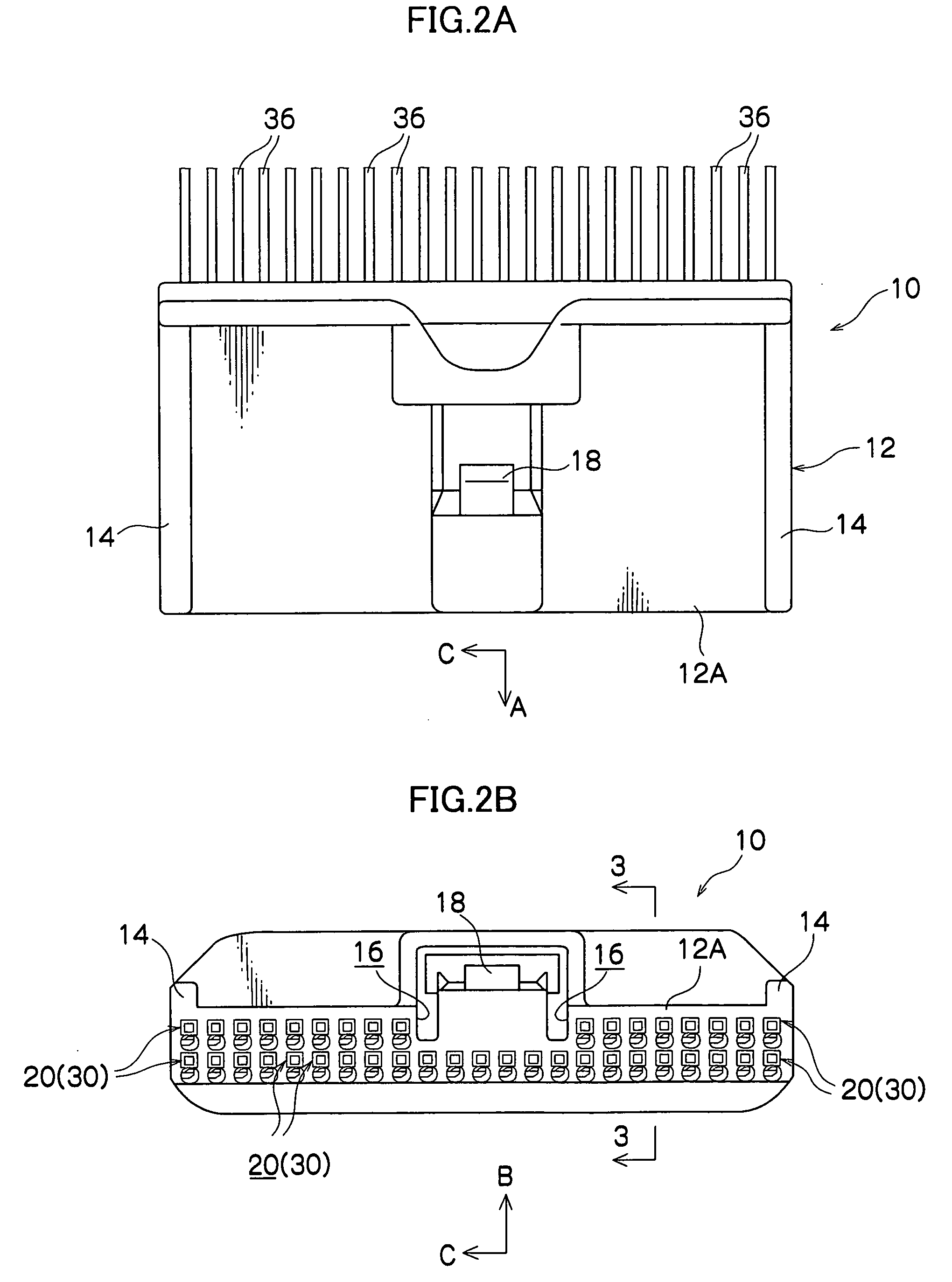
[0029]FIG. 2A shows a plan view of the connector 10, and FIG. 2B shows a front view of the connector 10.

[0030] As shown in these drawings, the connector 10 is equipped with a connector housing 12. A front portion of the connector housing 12 is formed as a fitting portion 12A, at which another connector, which is not shown, will be inserted. Specifically, in the present embodiment, the connector 10 serves as a female connector. The connector housing 12 is also provided with a pair of guide protrusion portions 14, a pair of guide recess portions 16, an anchoring projection 18 and so f...


PUM


Abstract

A connector enables a size reduction while maintaining a function of reliably preventing terminal members from falling out of terminal holes. In this connector, a plate spring piece is provided in a terminal hole of a connector housing, with a length thereof set to an axial direction of the terminal hole, and an engaging pawl protrudes from the plate spring piece. When a female terminal is inserted into the terminal hole, the engaging pawl engages with the female terminal and bends the plate spring piece downward, enabling the insertion. When the female terminal is inserted to a predetermined depth in the terminal hole, the plate spring piece returns and the engaging pawl moves into an engaging hole of the female terminal. The plate spring piece has a structure of which one length direction end portion and one side portion, along the length direction, are fixed to the connector housing.

Description

CROSS-REFERENCE TO RELATED APPLICATION [0001] This application claims priority under 35 USC 119 from Japanese Patent Application No. 2004-62248, the disclosure of which is incorporated by reference herein. BACKGROUND OF THE INVENTION [0002] 1. Field of the Invention [0003] The present invention relates to a connector which is structured by assembling a terminal member to a connector housing, and which connects with another connector. [0004] 2. Description of the Related Art [0005] A connector has been structured by assembling terminal members, which are formed of a conductive metallic material, into terminal holes formed in a connector housing, which is formed of an insulative resin material. This connector is connected to a similarly structured other connector for putting the terminal members into states of conductive connection with terminal members of the other connector, such that this state is maintained. The terminal members are assembled to the connector housing such that the...

Claims


Application Information

Patent Timeline
Patent Type & Authority Applications(United States)
IPC IPC(8): H01R13/42H01R13/514
CPCH01R13/4223
Inventor SASAKI, HAREHIDEOKAMOTO, REIKIKATO, YOSHIAKIMINAKATA, MASATONISHIDA, ATSUSHI
Owner KK TOKAI RIKA DENKI SEISAKUSHO
Why Eureka
Try Eureka