Occupant protection system for vehicle

Active Publication Date: 2005-09-15
DENSO CORP
View PDF9 Cites 12 Cited by
  • Summary
  • Abstract
  • Description
  • Claims
  • Application Information

AI Technical Summary

Benefits of technology

[0005] Accordingly, the present invention is made in view of the above problems. It is an object of the present invention

Problems solved by technology

And therefore, the rear crash may be erroneously detected and thereby an erroneous o

Method used


Image

  • Occupant protection system for vehicle
  • Occupant protection system for vehicle
  • Occupant protection system for vehicle

Examples


Embodiment Construction

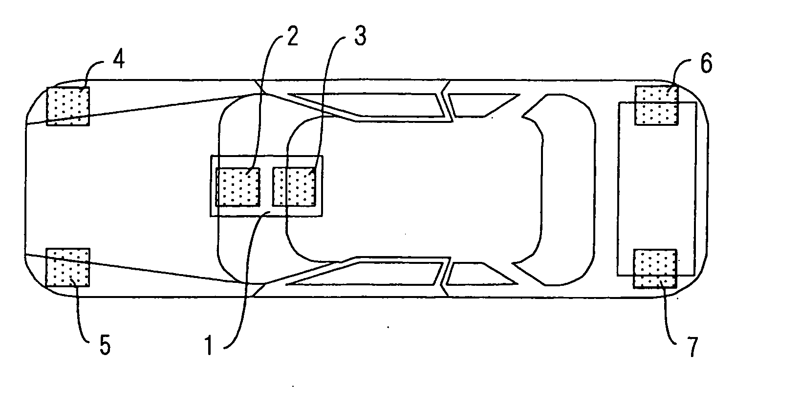
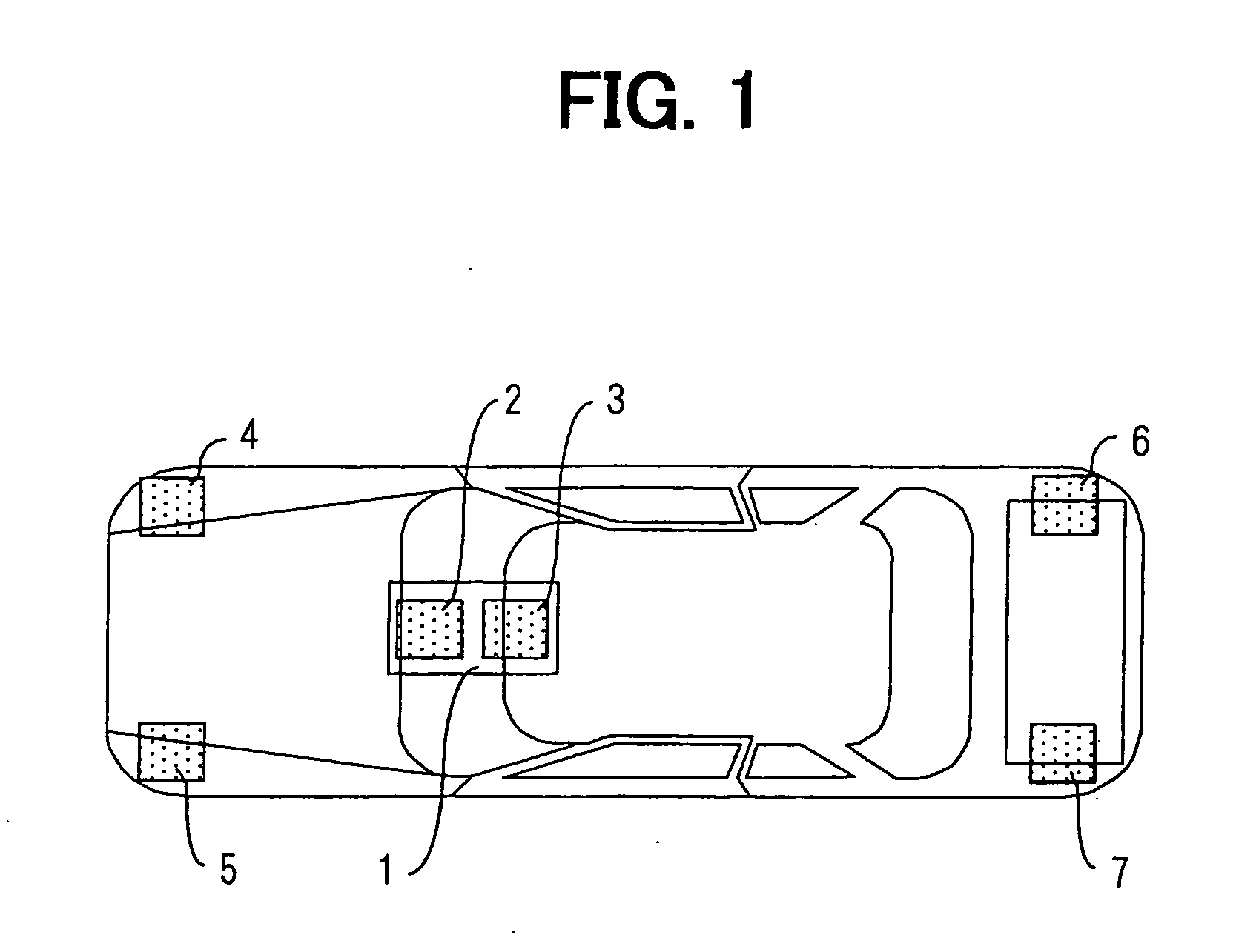
[0019] An embodiment of the present invention is explained with reference to FIG. 1. An occupant protection system comprises an electronic control unit (ECU) 1, a right-hand side front sensor 4, a left-hand side front sensor 5, a right-hand side back sonar sensor 6, a left-hand side back sonar sensor 7, a pretension device for a seatbelt (not shown), an unlock device for a door lock system, and an air-bag device for a rear crash.

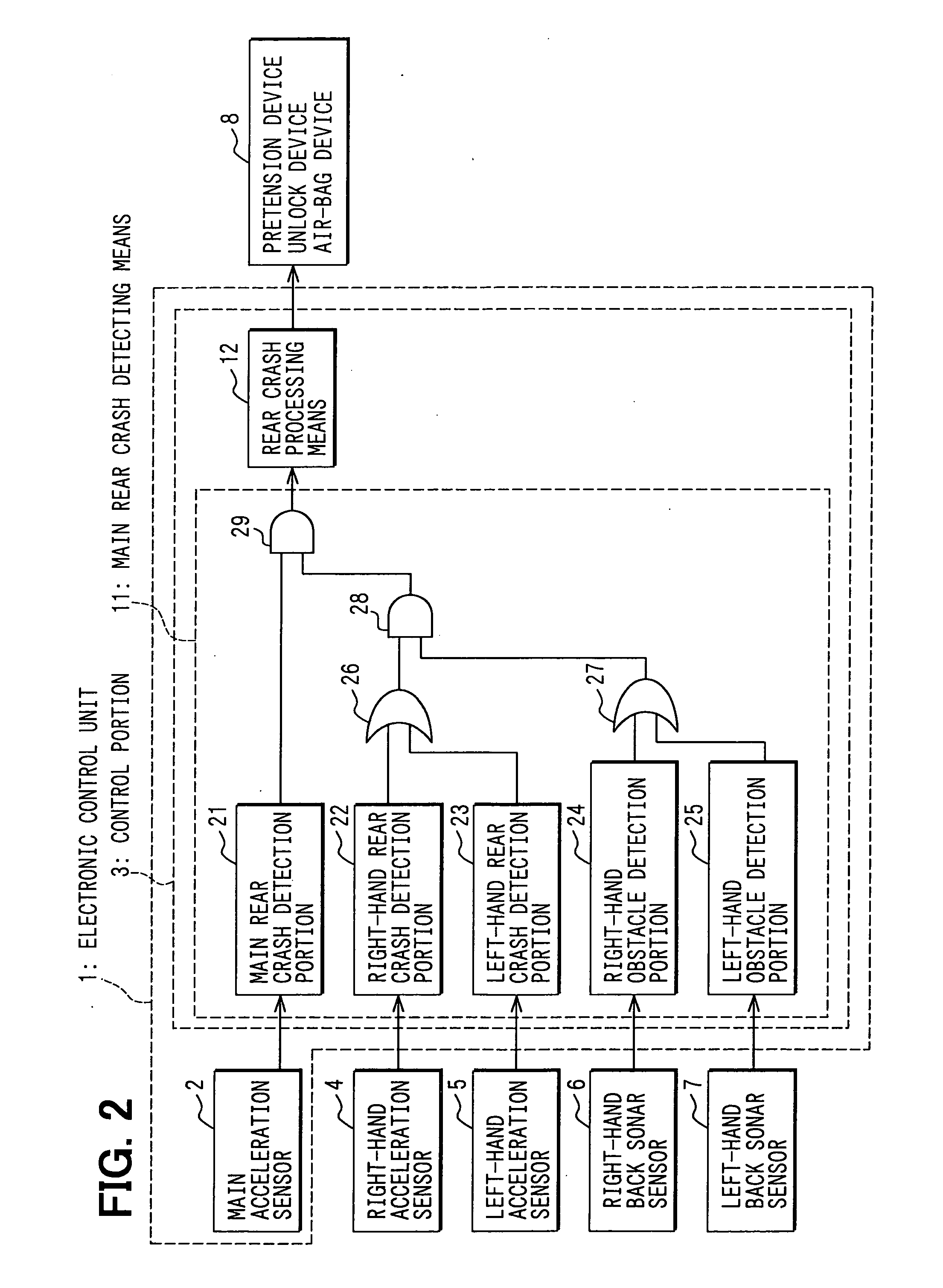
[0020] The ECU 1 is positioned at almost a center of a vehicle and has a main acceleration sensor 2 and a control portion 3, in which the sensor 2 detects acceleration in a longitudinal direction of the vehicle. The right-hand side and the left-hand side front sensors 4 and 5 are respectively positioned at a right-hand and a left-hand front sides of the vehicle, to detect the acceleration in the longitudinal direction of the vehicle. The front sensors 4 and 5 can also detect a front crash.

[0021] The above acceleration sensors 2, 4, and 5 are connected to t...


PUM


Abstract

An object of the invention is to provide an occupant protection system for a vehicle, in which an erroneous determination for a rear crash can be avoided. An output signal from an acceleration sensor for a front crash as well as an output signal from a back sonar sensor is also inputted to an electronic control unit (ECU), in addition to an output signal from a main rear crash sensor. Then, the ECU finally determines that a rear crash has occurred, only when the ECU respectively determines the rear crash from each of output signals from the main rear crash sensor, the front crash acceleration sensor and the back sonar sensor.

Description

CROSS REFERENCE TO RELATED APPLICATION [0001] This application is based on Japanese Patent Application No. 2004-67585 filed on Mar. 10, 2004, the disclosures of which is incorporated herein by reference. FIELD OF THE INVENTION [0002] The present invention relates to an occupant protection system for a vehicle, in particular an occupant protection system when a rear vehicle crashes against a front vehicle at its rear end. BACKGROUND OF THE INVENTION [0003] It is known in the art that a pretension device of a seat belt and / or an air-bag system for a rear crash are operated when the rear vehicle crashes against the front vehicle, as disclosed in Japanese Patent Publications Nos. 2002-283949 and 2004-058850. [0004] In the prior art system, a rear crash has been detected by one acceleration sensor assembled in an electronic control unit (ECU). And therefore, the rear crash may be erroneously detected and thereby an erroneous operation of the pretension device and / or the rear crash air-ba...

Claims


Application Information

Patent Timeline
IPC IPC(8): B60J5/00G01P15/00B60R21/00B60R21/01B60R21/16B60R22/48
CPCB60R21/0132B60R21/0134B60R2021/0011B60R2021/0004B60R21/0136
Inventor MIHARA, TAKASHIUENO, YUKIYASU
Owner DENSO CORP
Why Eureka
Try Eureka