This helps you quickly interpret patents by identifying the three key elements:
Problems solved by technology
Method used
Benefits of technology
Benefits of technology
This patent describes a system that can quickly detect changes in the frequency of a system and prevent incorrect detection of the frequency even if there is a disturbance in the system. This helps to improve the accuracy and reliability of the system.
Problems solved by technology
Therefore, for example, rapid output tracking for a change of the system frequency such as tracking with a delay of 40 msec or less, etc., is difficult.
However, there are cases where the calculated frequency temporarily oscillates greatly when a phase jump occurs in the system voltage.
Method used
Image
Click on the blue label to locate the original text in one second.
Reading with bidirectional positioning of images and text.
Examples
first embodiment
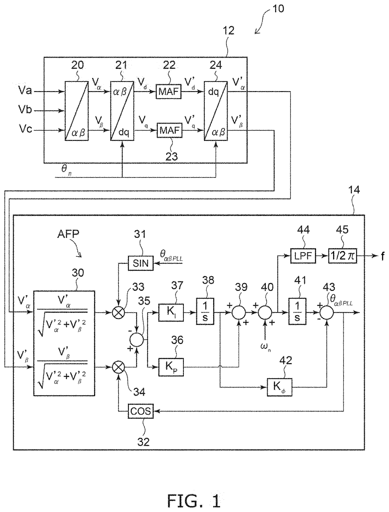
[0024]FIG. 1 is a block diagram schematically illustrating a system frequency detector according to a first embodiment.
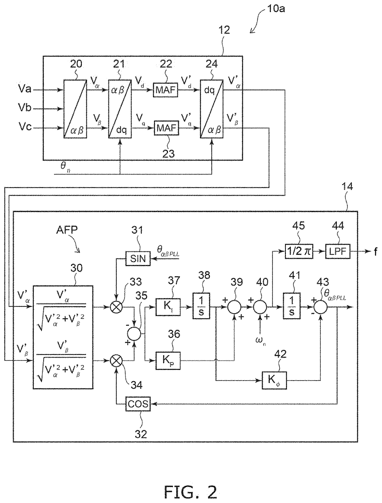
[0025]As illustrated in FIG. 1, the system frequency detector 10 includes an orthogonal coordinate signal generator 12 and a frequency calculator 14. The system frequency detector 10 detects the system frequency of a power system of three-phase alternating current power.
[0026]For example, the system frequency detector 10 is used in a power conversion device in which a distributed power source such as solar power generation, wind power generation, or the like is connected to a power system, etc. However, applications of the system frequency detector 10 are not limited thereto. The system frequency detector 10 can be used in any device in which it is necessary to detect the system frequency of a power system of three-phase alternating current power.
[0027]The orthogonal coordinate signal generator 12 generates orthogonal two-phase voltage signals Vα′ and Vβ′ from three...
second embodiment
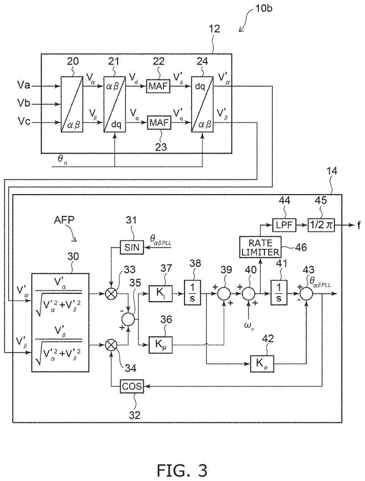
[0059]FIG. 3 is a block diagram schematically illustrating a system frequency detector according to a second embodiment.
[0060]In the system frequency detector 10b as illustrated in FIG. 3, the frequency calculator 14 further includes a rate limiter 46. The rate limiter 46 is provided in series with the arithmetic unit 45. For example, the rate limiter 46 is provided between the adder 40 and the low-pass filter 44 and is connected in series with the arithmetic unit 45 via the low-pass filter 44.
[0061]The rate limiter 46 limits a change of the system frequency f equal to or greater than a prescribed change rate by limiting a change of the angular frequency ω equal to or greater than a prescribed change rate. For example, the rate limiter 46 suppresses a change of the system frequency f equal to or greater than 25 Hz / sec.
[0062]Thus, by providing the rate limiter 46, even when a phase jump or the like occurs in the power system, an abrupt fluctuation of the system frequency f can be sup...
third embodiment
[0064]FIG. 4 is a block diagram schematically illustrating a system frequency detector according to a third embodiment.
[0065]In the system frequency detector 10c as illustrated in FIG. 4, the frequency calculator 14 further includes subtractors 47 and 48. The subtractor 47 is connected to the input and output sides of the rate limiter 46. The subtractor 47 subtracts the output value of the rate limiter 46 from the input value of the rate limiter 46. In other words, the subtractor 47 calculates the difference between the input value and the output value of the rate limiter 46. The difference between the output value of the rate limiter 46 and the input value of the rate limiter 46 is calculated by the subtractor 47 when the calculated value of the angular frequency ω abruptly increases, the angular frequency ω is limited by the rate limiter 46, and the output value of the rate limiter 46 becomes less than the input value of the rate limiter 46. The subtractor 47 inputs the calculatio...
PUM
Abstract
A system frequency detector includes an orthogonal coordinate signal generator generating an orthogonal two-phase voltagesignal from a three-phase voltagesignal of three-phase alternating current power of a power system by converting the three-phase voltage signal into a two-phase voltage signal orthogonal to the three-phase voltage signal, converting the two-phase voltage signal into a voltage signal of a rotating coordinate system, calculating a moving average of the voltage signal of the rotating coordinate system, and performing an inverse transformation of the voltage signal of the rotating coordinate system after calculating the moving average; and a frequency calculator including an angular frequencycalculator calculating an angular frequency of the power system based on the two-phase voltage signal, and an arithmetic unit calculating a system frequency of the power system from the angular frequency, the frequency calculator further including a low-pass filter provided in series with the arithmetic unit.
Description
TECHNICAL FIELD[0001]Embodiments of the invention relate to a system frequency detector.BACKGROUND ART[0002]A zero crossing point detection-type frequency calculation is known as a technique of detecting a system frequency of a power system. The zero crossing point detection-type frequency calculation can take measurement data only in intervals synchronized with the system frequency; ordinarily, a filter of a relatively long time constant of 200 msec or more has been provided to acquire resistance to system disturbances. Therefore, for example, rapid output tracking for a change of the system frequency such as tracking with a delay of 40 msec or less, etc., is difficult.[0003]Also, a frequency calculation using PLL (Phase Locked Loop) using a DQ transformation also is known. Such a frequency calculation using PLL can be used as a good frequency detector if there is no trouble at the power system side, and the system frequency can be tracked more quickly than the zero crossing point ...
Claims
Application Information
Patent Timeline
Application Date:The date an application was filed.
Publication Date:The date a patent or application was officially published.
First Publication Date:The earliest publication date of a patent with the same application number.
Issue Date:Publication date of the patent grant document.
PCT Entry Date:The Entry date of PCT National Phase.
Estimated Expiry Date:The statutory expiry date of a patent right according to the Patent Law, and it is the longest term of protection that the patent right can achieve without the termination of the patent right due to other reasons(Term extension factor has been taken into account ).
Invalid Date:Actual expiry date is based on effective date or publication date of legal transaction data of invalid patent.

