

Breathalyzer test device
a breathalyzer and test device technology, applied in the direction of instruments, chemical methods analysis, transportation and packaging, etc., can solve the problems of increased accident risk, inability to accurately test breathalyzer, and difficulty in obtaining breathalyzer results,
- Summary
- Abstract
- Description
- Claims
- Application Information
AI Technical Summary
Benefits of technology
Problems solved by technology
Method used
Image

Examples
Embodiment Construction
[0026]An embodiment of the breathalyzer test device according to the present invention will be described below with reference to the drawings.
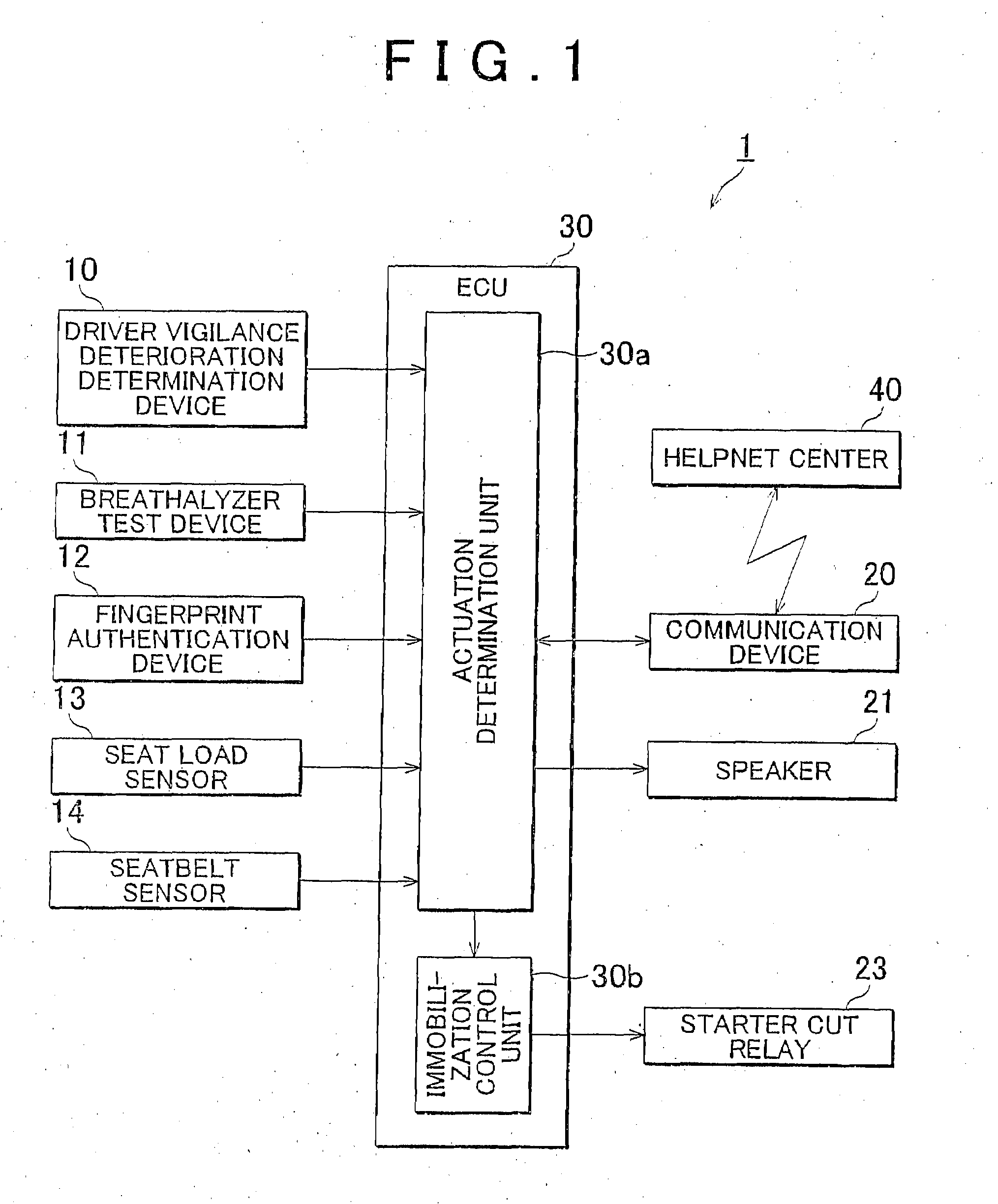
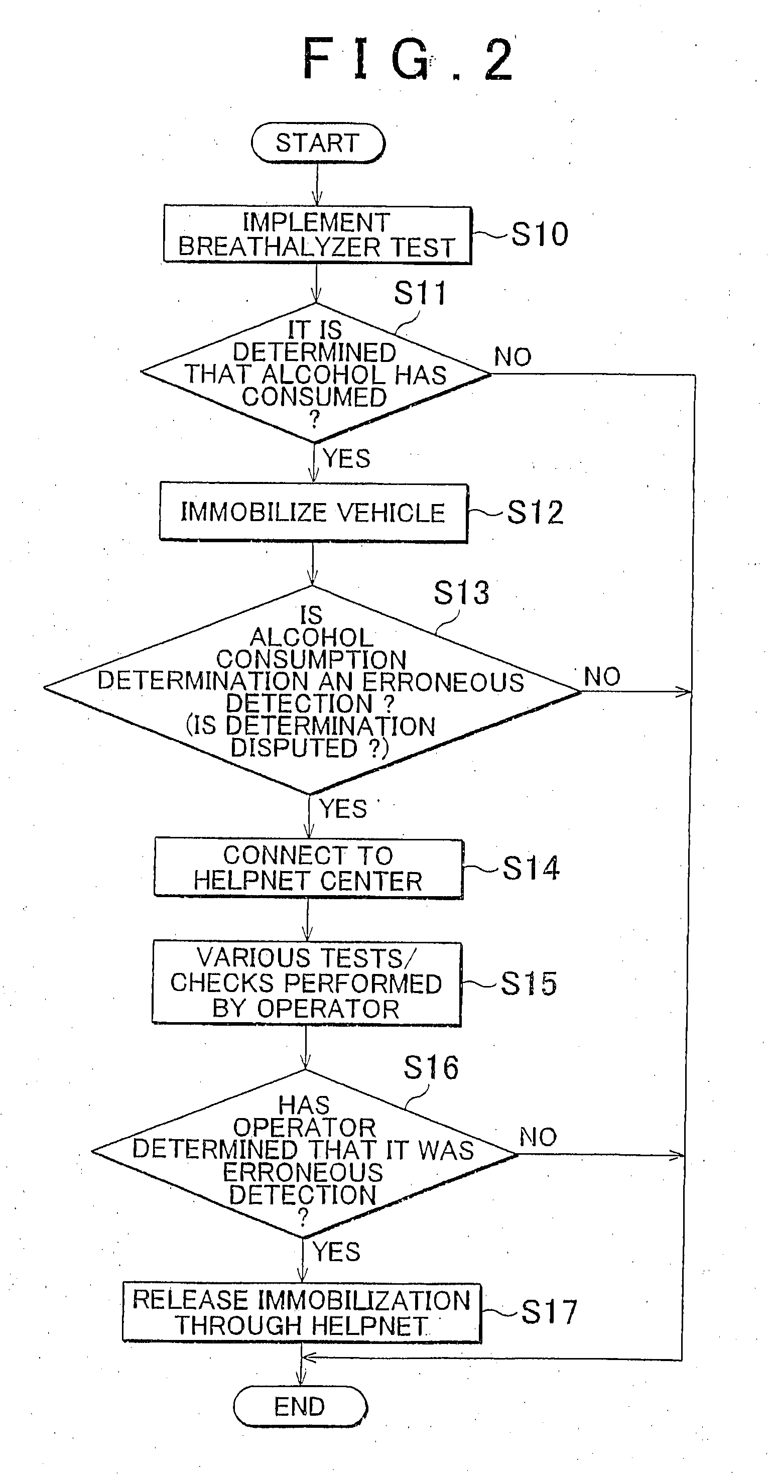
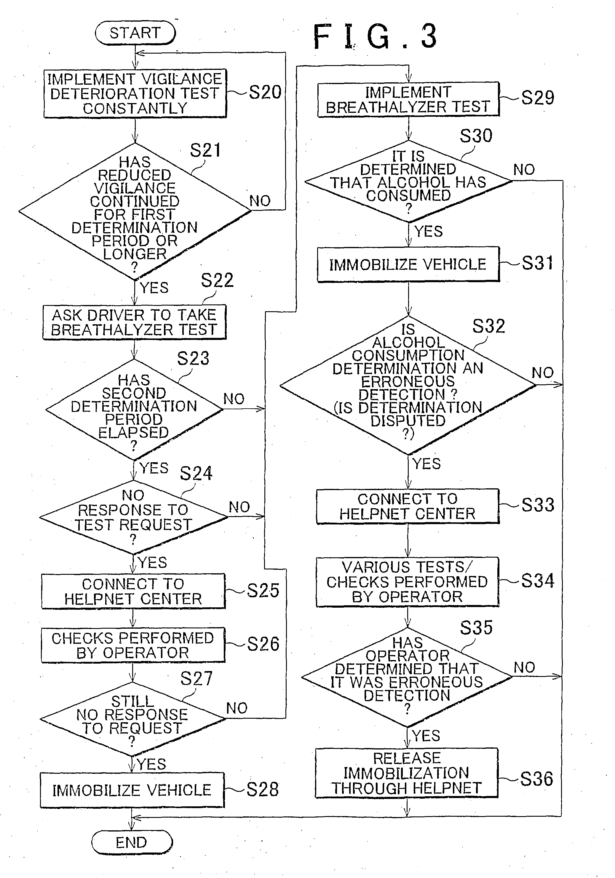
[0027]In this embodiment, the breathalyzer test device according to the present invention is applied to a drunk driving suppression device installed in a vehicle. The drunk driving suppression device according to this embodiment implements a breathalyzer test on a driver when testing is necessary, and immobilizes the vehicle when the driver has consumed alcohol. Further, the drunk driving suppression device according to this embodiment uses a “HELPNET” system, for example, and is capable of immobilizing the vehicle and releasing the immobilization via HELPNET.
[0028]The HELPNET system is a system for performing various types of support in relation to vehicles (passengers), such as reporting emergencies and so on, so that information may be exchanged through communication between a HELPNET center and the vehicle (transmitting means). With HELPNE...
PUM
 Abstract
Description
Claims
Application Information