Self-aligning aseptic flanged joint

a flange joint, self-aligning technology, applied in the direction of hose connection, coupling, cable termination, etc., can solve the problems of harmful microorganisms or other pathogenic organisms, presence or growth of harmful microorganisms, etc., to reduce maintenance costs and manufacturing downtime, and facilitate assembly and disassembly.

Inactive Publication Date: 2005-09-15
FLOW SMART
View PDF19 Cites 20 Cited by
  • Summary
  • Abstract
  • Description
  • Claims
  • Application Information

AI Technical Summary

Benefits of technology

[0017] The use of the outer retaining ring in the gasket assembly limits the axial impingement of the flanges, thereby insuring that a preselected, proper degree of compression of the deformable portion of the gasket assembly is achieved. Excessive tightening, which frequently causes undesirable extrusion and possible removal of deformable gasket material into the bore of the joint assembly, is effectively prevented. Misalignment or misplacement of the gasket assembly within the flange joint is likewise minimized.
[0018] The present flange joint system virtually eliminates the formation of traps in recesses of the joint in which process fluid can collect or stagnate, which frequently leads to the presence or growth of harmful microbes or other pathogenic organisms. The joint is easily assembled and disassembled to permit servicing, including replacement of the gasket assembly. The separability of the sealing member and the retaining ring of the gasket permit the former to be replaced and the latter, which is ordinarily more expensive to manufacture, to be reused. The joint is reliable and durable. The servicing can be carried out expeditiously by personnel who need not have a high level of skill, thereby lessening maintenance costs and manufacturing downtime.

Problems solved by technology

The present flange joint system virtually eliminates the formation of traps in recesses of the joint in which process fluid can collect or stagnate, which frequently leads to the presence or growth of harmful microbes or other pathogenic organisms.

Method used


Image

  • Self-aligning aseptic flanged joint
  • Self-aligning aseptic flanged joint
  • Self-aligning aseptic flanged joint

Examples


Embodiment Construction

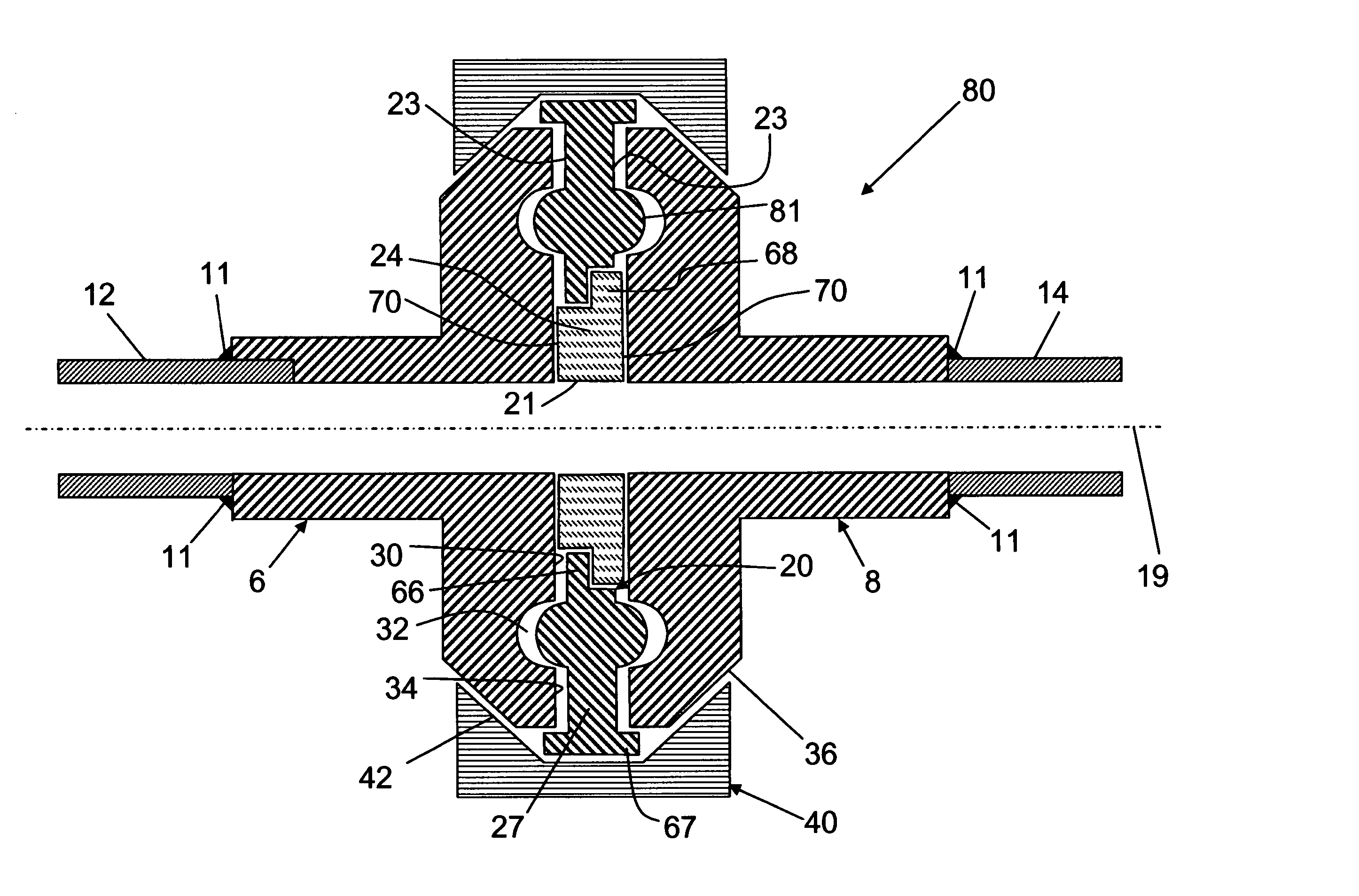
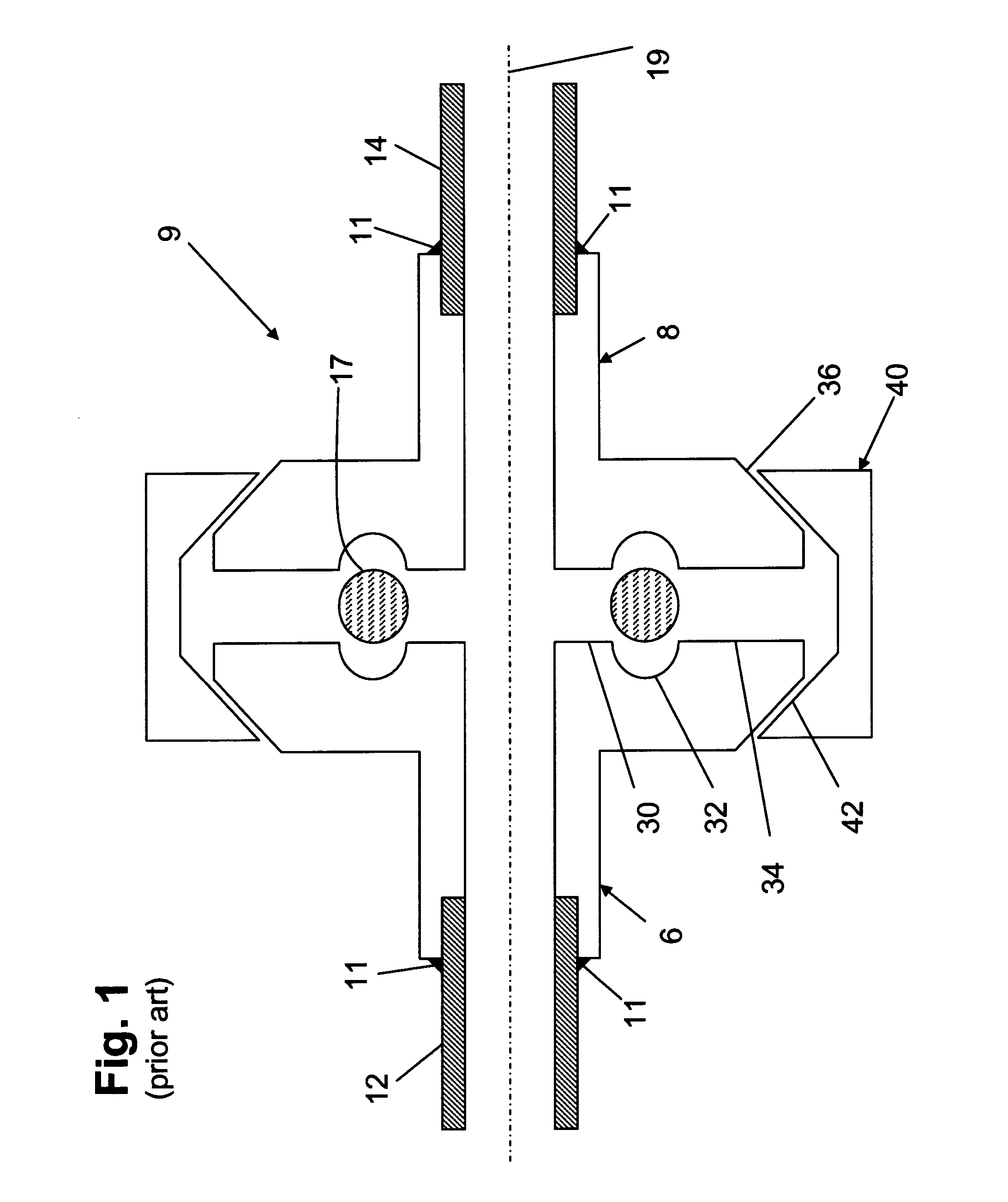
[0034] Referring to FIG. 3 there is depicted an embodiment of a flanged joint system of the invention. Joint 10 connects generally first and second cylindrical tubes 12, 14, which are welded 11 to first and second flanges 16, 18 (also known as ferrules). Alternatively, the tubes may be attached by any other suitable method, non-exclusively including brazing, soldering, threaded connection, or any other similar technique that provides a durable, leak-resistant connection. Flanges 16 and 18 adjoin in end-to-end relationship about a common center axis 19. The flanges are substantially identical and have mating surfaces generally perpendicular to axis 19. Opposite the mating surfaces are clamping surfaces that include tapered portions 36, which cooperate to form a generally frustoconical outer peripheral surface when the flanges are juxtaposed. The joint is sealed using gasket assembly 20, which comprises a generally annular, rigid retaining ring 22 that is removably engaged with deform...


PUM


Abstract

A flanged joint system connects two pipes disposed along a common axis. A flange having a mating surface terminates each pipe. A gasket assembly comprising an outer annular, substantially rigid retaining ring and a peripheral alignment rim, an inner deformable annular sealing member is interposed between the mating surfaces of the flanges. The flanges and gasket assembly are aligned in mutually coaxial relationship by receipt of the flanges within the alignment rim. The flanges are clamped together with their mating surfaces in axially aligned, facing relationship. The retaining ring limits the impingement of the flanges and prevents overcompression of the deformable material. The joint is reliable and durable, and permits aseptic processing conditions to be maintained. Servicing and gasket replacement are readily accomplished.

Description

[0001] This application claims the benefit of U.S. Provisional Application No. 60 / 553,259, filed Mar. 15, 2004.BACKGROUND OF THE INVENTION [0002] 1. Field of the Invention [0003] This invention relates to the joining of tubes or pipes, and more particularly, to an aseptic flanged joint between pipes employing a self-aligning rigid retaining ring surrounding a gasket and limiting the deformation thereof. [0004] 2. Description of the Prior Art [0005] Flanged joints are widely used to interconnect tubes or pipes conveying a variety of fluids, including gases, liquids, liquids also containing solid or semi-solid matter, or other fluid-like media. The tubes may be either pressurized or under vacuum. The joints connect extended sections of tubes, as well as joining tubes to fittings, couplers, valves, pumps, inspection ports, and other related devices. An ideal joint is easily assembled with minimal cost and labor, and is capable of operating reliably under any conditions reasonably antic...

Claims


Application Information

Patent Timeline
Patent Type & Authority Applications(United States)
IPC IPC(8): F16L35/00
CPCF16L23/02F16L2201/44F16L23/04F16L23/036
Inventor BONGIORNO, LOUIS C.
Owner FLOW SMART
Why Eureka
Try Eureka