Self light emitting display module, electronic equipment into which the same module is loaded, and inspection method of a defect state in the same module

Inactive Publication Date: 2005-09-15
TOHOKU PIONEER CORP
View PDF5 Cites 18 Cited by
  • Summary
  • Abstract
  • Description
  • Claims
  • Application Information

AI Technical Summary

Benefits of technology

[0010] The present invention has been developed as attention to the above-described realistic problems has been paid, and it is an object of the present invention to provide a self light emitting display module which is provided with a detection means which can inspect whether or not there is a defect

Problems solved by technology

For example, regarding injection equipment for a medicine or the like, in the case where a bright leak phenomenon occurs in the scan direction on a portion displaying figures showing an injection amount, a problem that whether a displayed figure is “0” or “8” cannot be determined may occur.
A problem which may occur is that pixels of a part on which a decimal point is displayed are not lit so that the figures are read while that a place for figures is erroneously displayed is not being noticed, or the like.
It is extremely dangerous for a user to keep using the above-described equipment while perceiving display in a troubled state being normal, and it is needless to say that such a state may cause a serious problem.
In a case where the evaluation device disclosed in Japanese Patent Publication No. 3437152 is utilized, although an effect that an initial defect of a product can be detected to deal with the defect before the display panel having the

Method used


Image

  • Self light emitting display module, electronic equipment into which the same module is loaded, and inspection method of a defect state in the same module
  • Self light emitting display module, electronic equipment into which the same module is loaded, and inspection method of a defect state in the same module
  • Self light emitting display module, electronic equipment into which the same module is loaded, and inspection method of a defect state in the same module

Examples


first embodiment

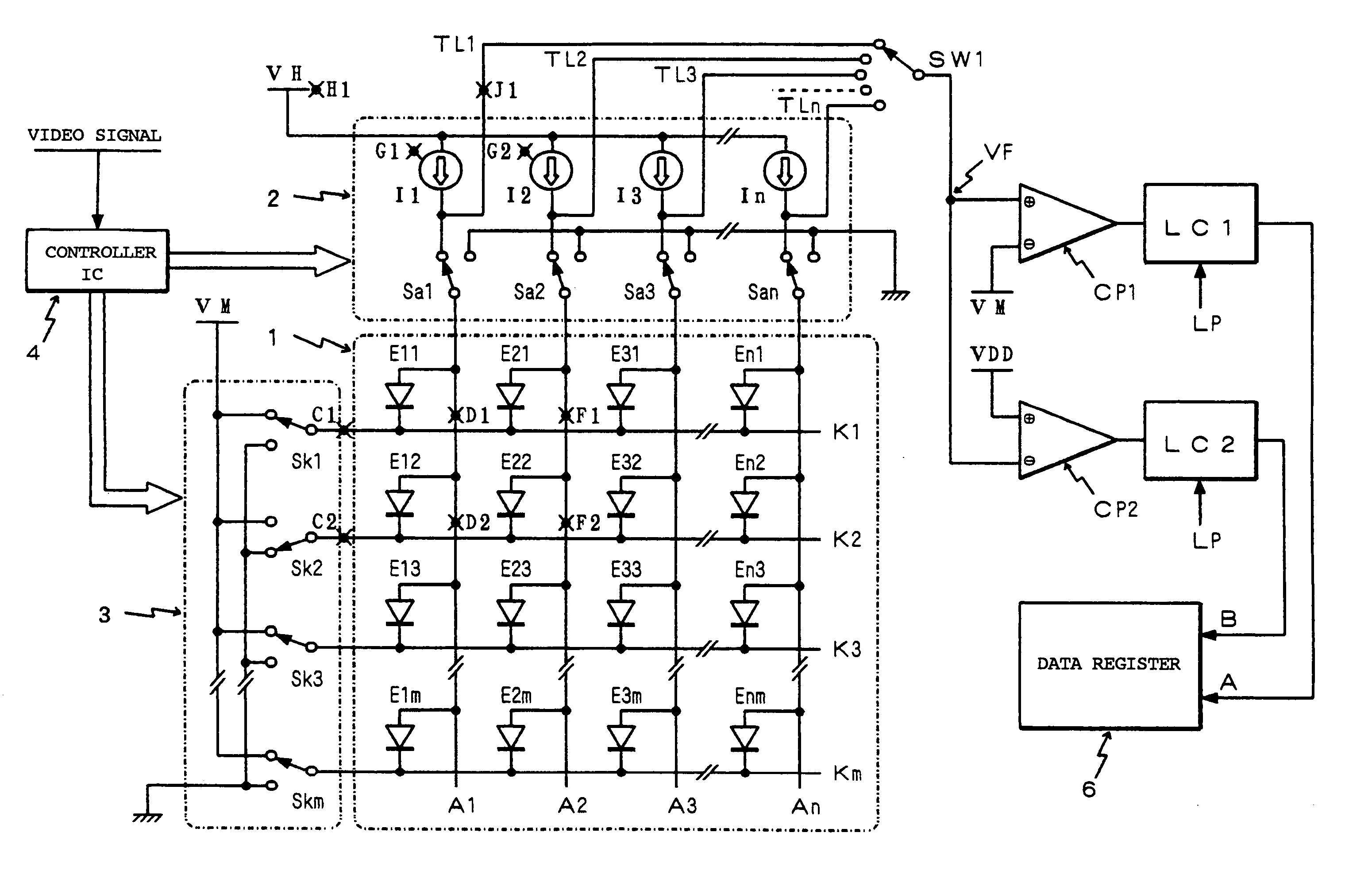
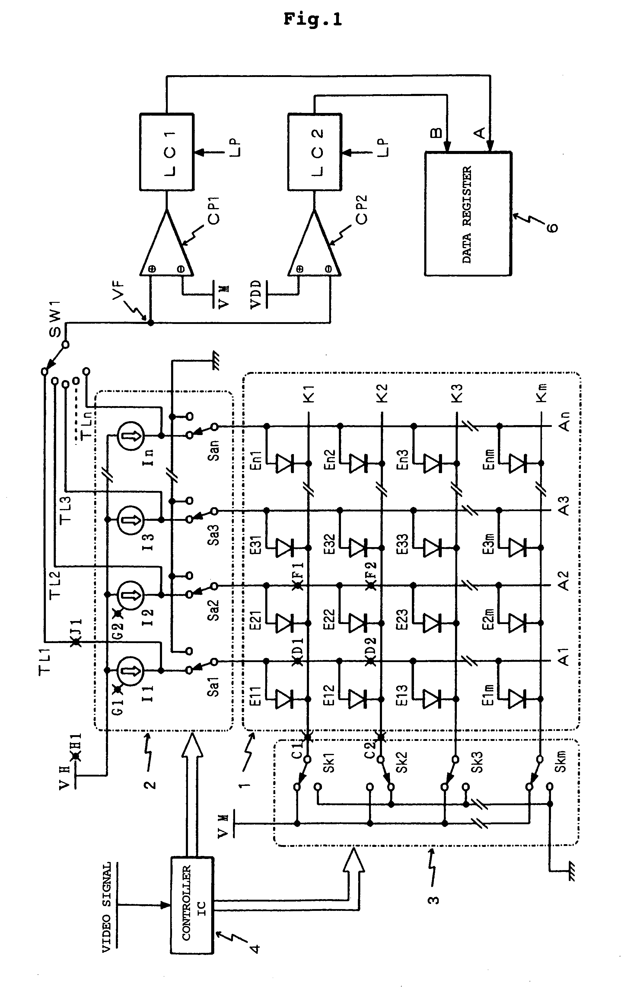
[0020]FIG. 1 shows a self light emitting module according to the present invention, and this shows an example employing the passive matrix type display panel. As drive methods for organic EL elements in this passive matrix type drive method, there are two methods, that is, cathode line scan / anode line drive and anode line scan / cathode line drive, and the structure shown in FIG. 1 shows a form of the former cathode line scan / anode line drive. That is, anode lines A1-An as n data lines are arranged in a vertical direction (column direction), cathode lines K1-Km as m scan lines are arranged in a horizontal direction (row direction), and organic EL elements E11-Enm designated by symbols of diodes are arranged at positions at which the anode lines intersect the cathode lines (in total, n×m portions) to construct a display panel 1.

[0021] In the respective EL elements E11-Enm constituting pixels, one ends thereof (anode terminals in equivalent diodes of EL elements) are connected to the an...

second embodiment

[0046]FIG. 4 shows a self light emitting display module according to the present invention, and this also shows an example employing a passive matrix type display panel similarly. In this FIG. 4, parts corresponding to respective parts shown in FIG. 1 are designated by the same reference characters, and therefore detailed description thereof will be omitted.

[0047] In the embodiment shown in this FIG. 4, the output terminal potentials of the respective constant current sources I1-In selected by the select switch SW1 are supplied to the noninverting input terminal in one comparator CP1 constituting the voltage comparison means. A reference potential generation means 5 constructed such that the voltage value thereof is changeable is connected to the inverting input terminal of this comparator CP1. This reference potential generation means 5 functions to output an analog voltage whose value corresponds to inputted digital data by the inputted digital data.

[0048] In the embodiment shown...


PUM


Abstract

Provided is a self light emitting display module by which defect can be reported to a user immediately in a case where defect occurs for example in a pixel of a light emitting display panel. Output terminal potentials of constant current sources I1-In which supply constant currents to respective EL elements E11-Enm arranged in a light emitting display panel 1 are drawn via inspection lines TL1-TLn and are selected by a select switch SW1. A selected electrical potential is supplied to first and second comparators CP1, CP2 whose comparison reference potentials differ, and their comparison results are latched by latch circuits LC1, LC2 respectively to be stored in a data register 6 provided as a memory means. A determination is made as to whether or not defect has occurred in a portion of a part including the respective EL elements and respective drivers 2,3 through data stored in the data register 6.

Description

BACKGROUND OF THE INVENTION [0001] 1. Field of the Invention [0002] The present invention relates to a self light emitting display module provided with a light emitting display panel in which for example organic EL (electroluminescent) elements are employed for pixels as self light emitting elements and drive means to drive and light this panel, and particularly to a self light emitting display module having a function that can inspect a defect state in the light emitting display panel, the lighting drive means, a connecting portion between the light emitting display panel and the lighting drive means, or the like and to an inspection method of a defect state in the same module. [0003] 2. Description of the Related Art [0004] A display has been installed in many of electronic equipment or the like which have been provided presently, and this display has been necessary and indispensable as a man-machine interface of equipment supporting information-oriented society. In a case where t...

Claims


Application Information

Patent Timeline
IPC IPC(8): G09F9/00G01R31/00G09G3/20G09G3/30G09G3/32H01L51/50H05B33/12
CPCG09G2320/0209G09G2320/043G09G2330/10G09G2310/0256G09G3/32G09G3/3216G09G3/3275G09G2330/12
Inventor GOTO, TAKASHISATO, HIROYUKISATOH, KAZUHIRO
Owner TOHOKU PIONEER CORP
Why Eureka
Try Eureka