
Communication system and apparatus, and control method therefor

a communication system and apparatus technology, applied in the field of mobile communication systems, can solve the problems of poor reception quality, system work well, and optimization cannot be obtained by merely selecting one of a plurality of antennas, and achieve the effect of optimizing or improving quality

Inactive Publication Date: 2005-09-15
NEC CORP
View PDF44 Cites 12 Cited by
  • Summary
  • Abstract
  • Description
  • Claims
  • Application Information

AI Technical Summary

Benefits of technology

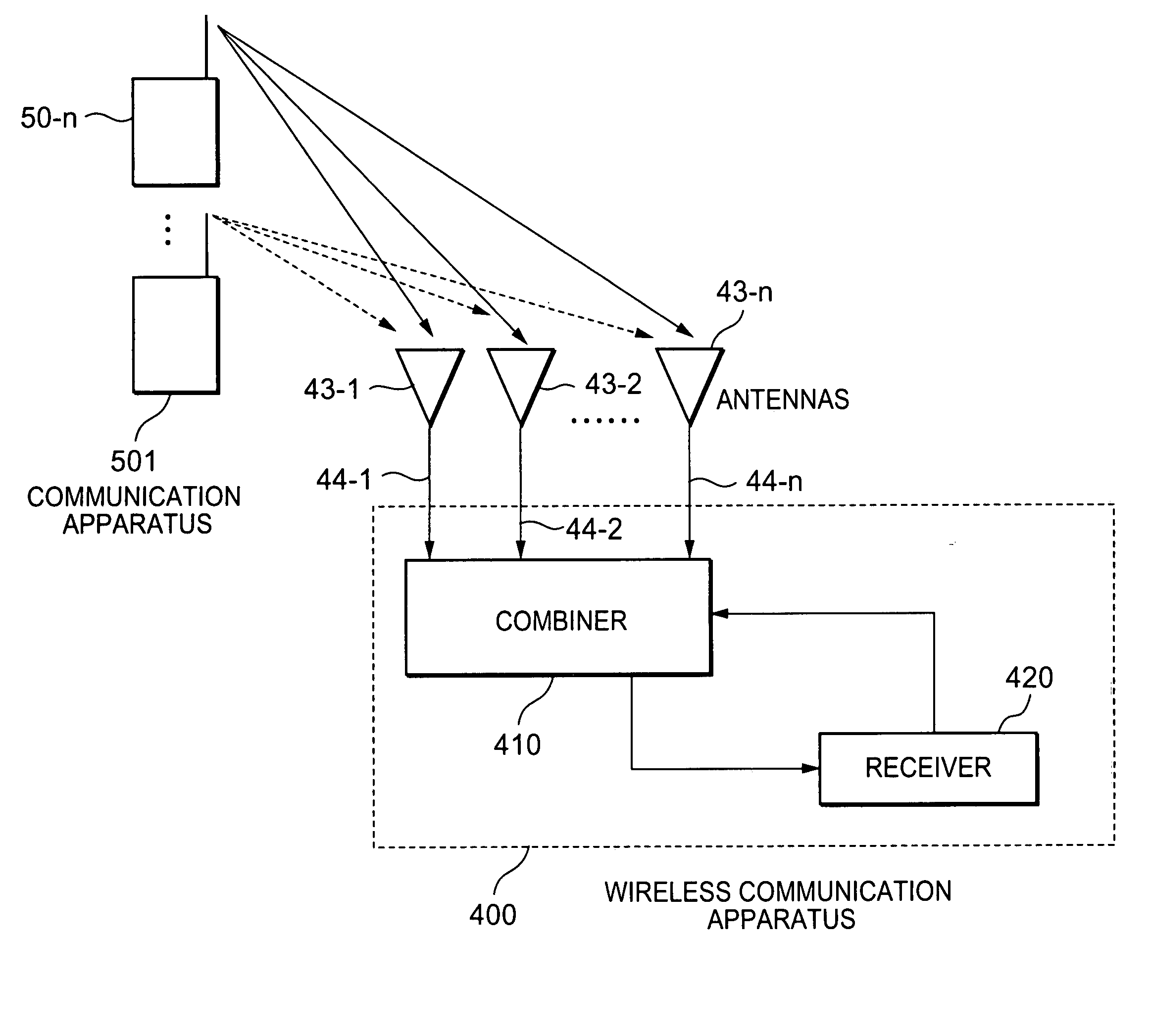
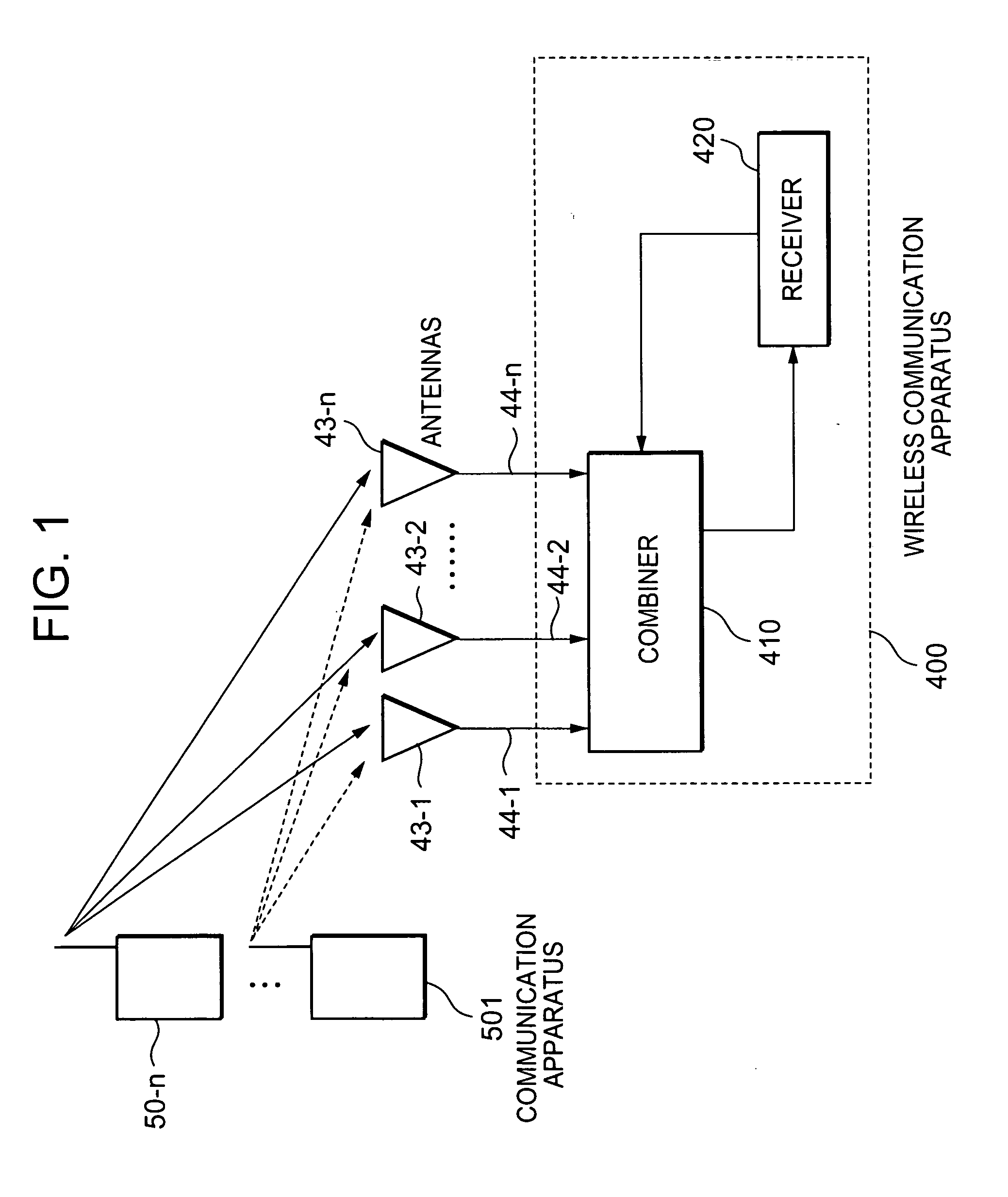
[0008] In order to solve the above-noted problems associated with conventional communication systems and to provide improved communication systems, the present invention provides a communication system in which a wireless communication apparatus, equipped with a plurality of antennas, may optimize or improve quality based on a plurality of reception signals as a whole. The present invention also provides a communication system in which a wireless communication apparatus, equipped with a plurality of antennas, may optimize or improve quality based on a transmission signal. In addition, the present invention provides a communication system in which a wireless communication apparatus, equipped with multiple antennas, may have a single reception circuit.

Problems solved by technology

According to the system of FIG. 14, the use of only a single antenna may result in poor reception quality.
However, this system works well only if the receiving apparatus is receiving only a single signal at a time from a single transmission apparatus.
However, such an optimization can not be obtained by merely selecting one of a plurality of antennas based on the reception quality of a single signal, because the plurality of signals from the plurality of transmission apparatuses are received via numerous signal paths and the best antenna may be different for each signal.

Method used


Image

  • Communication system and apparatus, and control method therefor
  • Communication system and apparatus, and control method therefor
  • Communication system and apparatus, and control method therefor

Examples


first embodiment

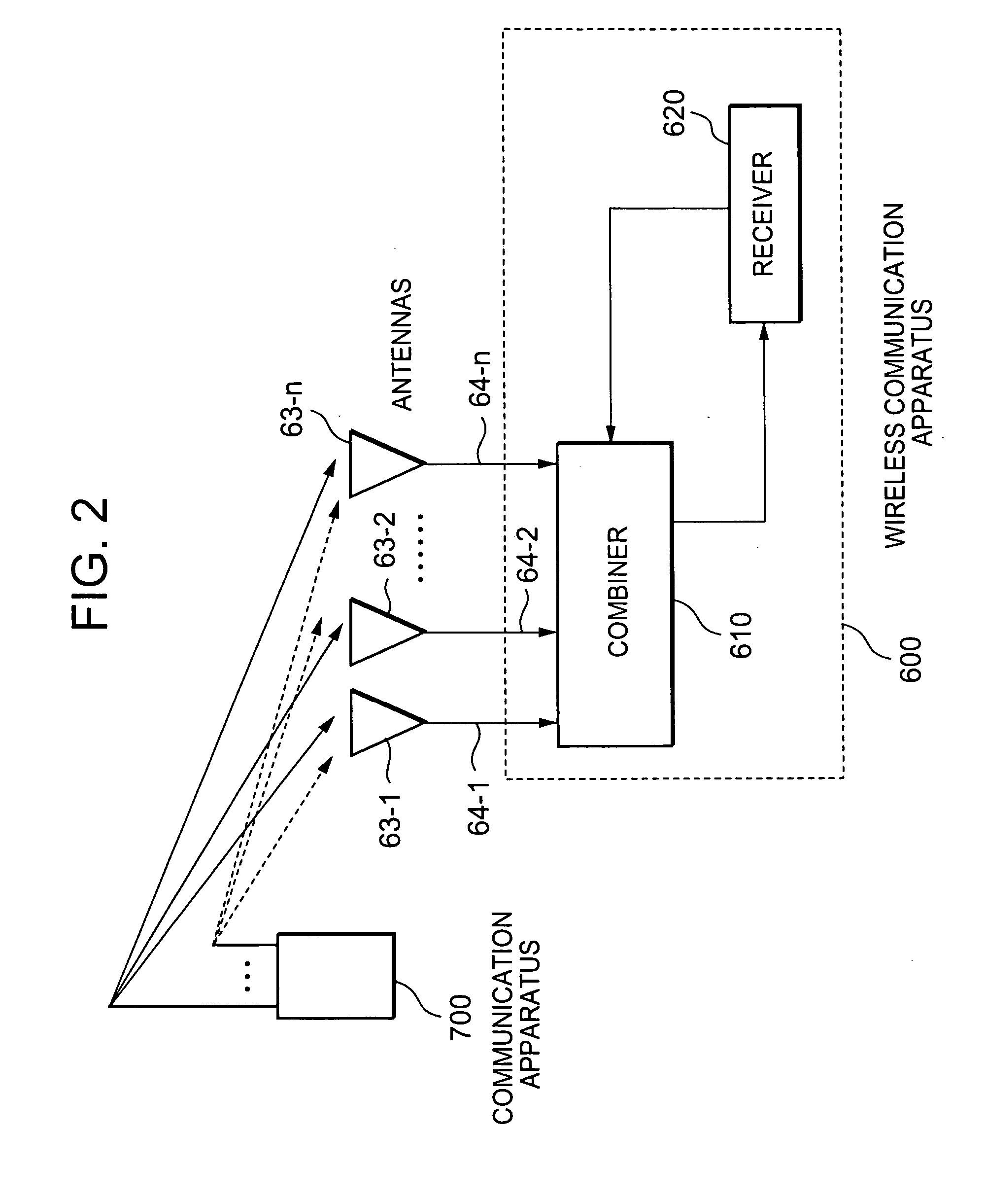
[0037] The combiner 610 may weight the signals 64-1 to 64-n and add them to form the combined signal. The weights may be fixed or variable, as described with respect to the

[0038] Further, as described with respect to the first embodiment, the receiver 620 may transmit information about the reception signals to the combiner 610, and the transmission powers of the reception signals transmitted from the communication apparatus 700 may be controlled by a closed loop power control between the wireless communication apparatus 600 and the communication apparatus 700.

[0039] Accordingly, as described with respect to the first embodiment, the combiner 610 may control the variable weights assigned to reception signals 64-1 to 64-n, based on the transmission powers of the reception signals transmitted from the communication apparatus 700.

[0040] Also as described with respect to the first embodiment, the combiner 610 may control the variable weights at regular intervals or at certain specific ...

fourth embodiment

[0056] According to an alternative aspect of the fourth embodiment, the combiner / divider 1010 may divide the transmission signals into the transmission signals 106-1 to 106-n in a variable ratio and may weight the reception signals 104-1 to 104-n based on the variable ratio associated with the transmission signals 106-1 to 106-n. The combiner / divider 1410 may control the variable ratio based on the received information relating to the transmission powers of the transmission signals 106-1 to 106-n or of the reception signals 104-1 to 104-n. For example, the combiner / divider 1010 may control the variable ratio with the aim of reducing one of: a maximum transmission power of the transmission (or reception signals); an average transmission power of the transmission (or reception) signals; a fluctuation of the average transmission power of the transmission (or reception) signals; a difference between the maximum transmission power and the minimum transmission power of the transmission (o...

second embodiment

[0059] The communication apparatus 1300 is similar in function and design to the communication apparatus 700 of the second embodiment and therefore will not be described again in detail.

[0060] The wireless communication apparatus 1200 comprises a combiner / divider 1210, a receiver 1220, a transmitter 1250, and plurality of antennas 123-1 to 123-n. where n is two or more. The antennas 123-1 to 123-n receive the reception signals transmitted from the communication apparatus 1301. In addition, the antennas 123-1 to 123-n send to the combined signals 124-1 to 124-n, respectively, which are generated from the reception signals. Further, the antennas 123-1 to 123-n receive transmission signals 126-1 to 126-n from the combiner / divider 1210, and transmit them to the communication apparatus 1301. The combiner / divider 1210 receives the reception signals-124-1 to 124-n from the antennas 123-1 to 123-n and combines them to produce a combined signal, which is transmitted to the receiver 1220. Fur...


PUM


Abstract

A wireless communication apparatus comprises: a plurality of antenna means for receiving a wireless reception signal from a secondary communication apparatus; and a combining means for combining signals from the plurality of antennas to from a combined signal or for selecting one of the signals from the plurality of antennas. A wireless communication apparatus comprises: a plurality of antenna means for transmitting a wireless transmission signal to a secondary communication apparatus; and a dividing means for dividing a transmission signal into plurality of transmission signals to be transmitted by the plurality antennas means or for selecting one of the plurality of antenna means to transmit the transmission signal.

Description

BACKGROUND OF THE INVENTION [0001] Priority is claimed from Japanese Patent Application No. 067901 / 2004, filed Mar. 10, 2004, the content of which is incorporated herein by reference. [0002] 1. Field of Invention [0003] The present invention relates to a mobile communication system, and in particular, to transmission and reception diversity technologies. [0004] 2. Description of the Related Art [0005]FIG. 14 shows a wireless communication system in which a receiving apparatus 05 receives wireless signals from a transmitting apparatus 01 and / or 02 by means of an antenna 04. In the event of using only one antenna to receive signals, as shown in FIG. 14, there may be interference between signals, and thus the receiving power may be significantly reduced. Specifically, interference may occur between a direct wave a (or b) which is an electric wave transmitted from apparatus 01 (or 02) having directly reached the receiving antenna 04 and a reflected wave a′ (or b′) which is the electric ...

Claims


Application Information

Patent Timeline
Patent Type & Authority Applications(United States)
IPC IPC(8): H04B7/08H04B7/02H04B7/04H04B7/06H04B7/26H04L1/02
CPCH04W52/08H04B7/0857H04B7/04
Inventor IWASAKI, MOTOYANISHIMURA, OSAMIHIRADE, SEIHASEBA, YUKIO
Owner NEC CORP
Learn More