DC connector assembly

a technology of dc connectors and connectors, applied in the direction of coupling contact members, coupling device connections, connection contact member materials, etc., can solve the problems of adding complexity and cost to the connector, users may have difficulty manipulating buttons or latches, and the distance of so as to minimize the insertion extraction force and minimize the distance the plug has to travel.

Active Publication Date: 2005-09-15
APPLE INC
View PDF10 Cites 133 Cited by
  • Summary
  • Abstract
  • Description
  • Claims
  • Application Information

AI Technical Summary

Benefits of technology

[0010] The invention relates, in another embodiment, to a DC connector arrangement. The DC connector arrangement includes a DC receptacle. The DC connector arrangement also includes a DC plug insertable into the DC receptacle. The DC connector arrangement further includes a holding detent mechanism located between the DC receptacle and DC plug. The holding detent mechanism minimizes the distance the plug has to travel relative to the receptacle at the friction force required to hold the plug in the receptacle during normal use.
[0011] The invention relates, in another embodiment, to a DC connector assembly. The DC connector assembly includes a DC receptacle having a receiving element. The DC connector assembly also includes a DC plug having an insertion element that both mechanically and electrically couples to and deco...

Problems solved by technology

Unfortunately, however, this makes it difficult to insert and extract the post to and from the jack.
While these mechanisms may work well, they add complexity and cost to the connector.
Furthermore, because they are mechanical in nature they can break over time (repeated use) and some users may have difficulty manipulating the buttons or latches.
Mor...

Method used


Image

  • DC connector assembly
  • DC connector assembly
  • DC connector assembly

Examples


Embodiment Construction

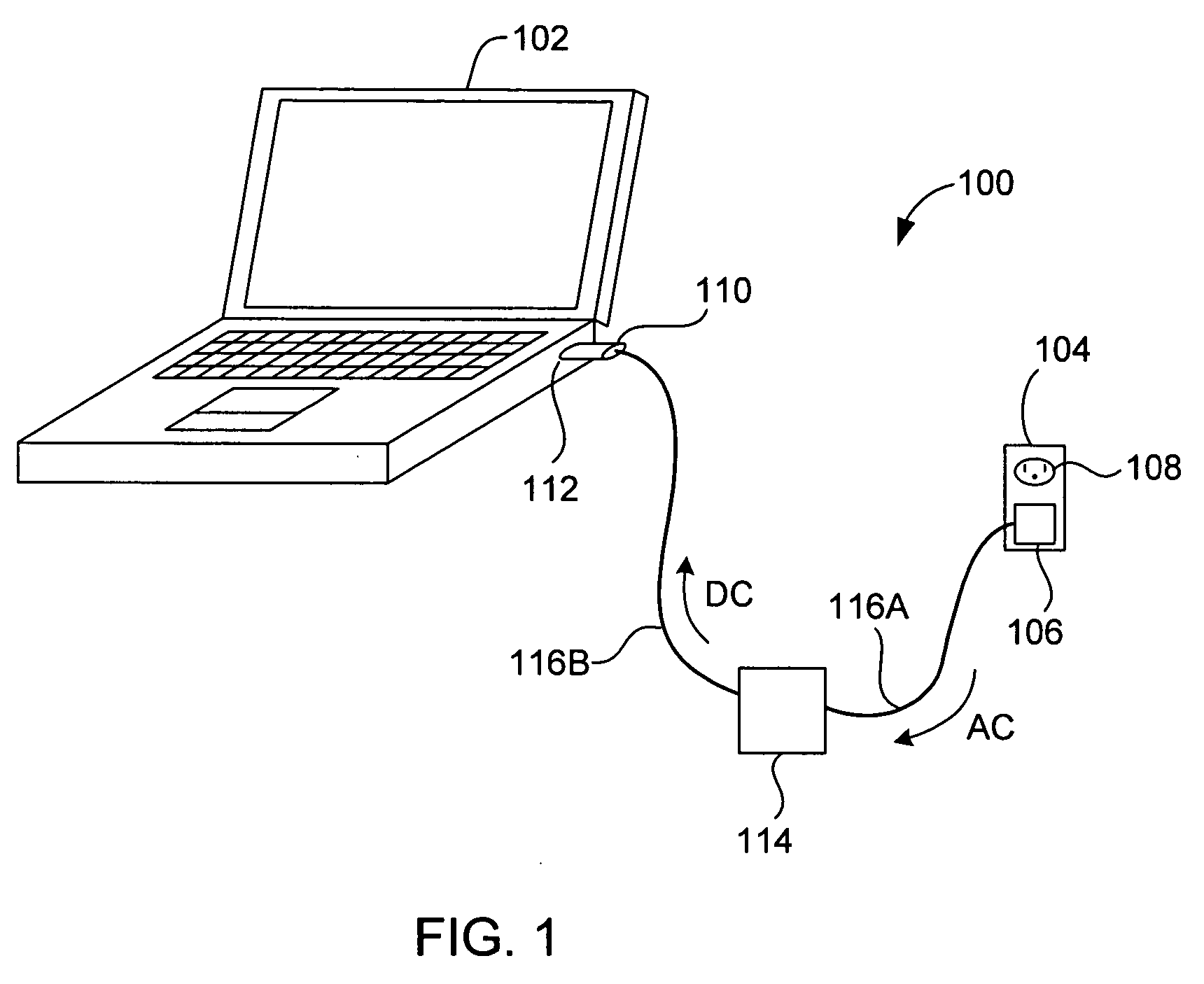
[0021] In electronic devices such as portable computers, the trend of thinner, lighter and powerful presents a continuing design challenge in the design of DC power connections. The design challenge generally arises from the desire to produce small and durable connections while still providing proper electrical contact, proper holding power during use, minimized insertion and extract forces, and easy connectability.

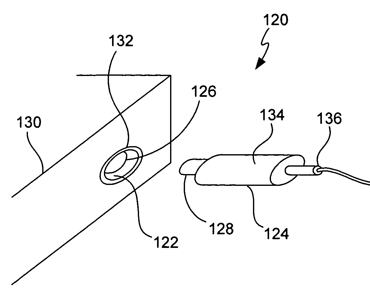
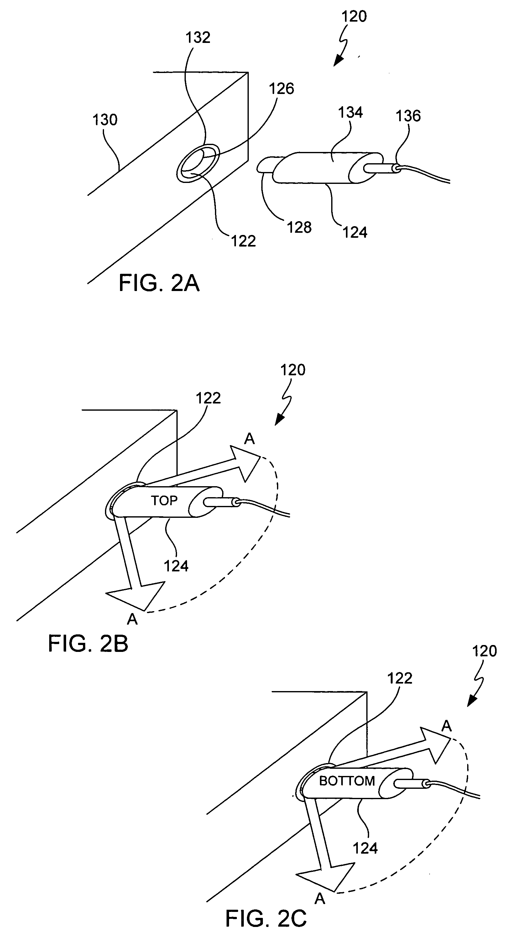
[0022] The invention generally pertains to DC connectors including DC plugs and DC receptacles. One aspect of the invention relates to DC plugs that are capable of being inserted into DC receptacles at two positions as for example 0 and 180 degrees (even though the electrical contacts are not electrically identical). Another aspect of the invention relates to DC plugs and receptacles with optimized insertion and extraction forces. The insertion and extract forces may be optimized by minimizing the distance the plug has to travel relative to the receptacle and including r...


PUM


Abstract

A DC connector arrangement is disclosed. The DC connector arrangement includes a DC plug and a DC receptacle that are configured to engage one another at more than one position. The DC plug and DC receptacle are also configured with a small contact distance to minimize the insertion and extraction forces that occur between the DC plug and the DC receptacle.

Description

FIELD OF THE INVENTION [0001] The present invention relates to apparatus and methods for powering electronic devices. More particularly, the present invention relates to improved techniques for DC connections. BACKGROUND OF THE INVENION [0002] In order to operate and / or charge electronic devices, dedicated power assemblies that connect the electronic devices to external power sources are required. Power assemblies generally include a plug that receives AC current from an electrical outlet, a power converter that turns AC current into DC current, and a power plug that distributes the DC current through a power port of the electronic device. As is generally well known, DC current (3 to 12 volts and less than 1 amp of current) is required to operate most electronic devices and to recharge batteries that store DC current while AC current (110 volts or 220 volts) is typically supplied in most buildings. [0003] AC connections, such as the American standard for alternating current, come in...

Claims


Application Information

Patent Timeline
IPC IPC(8): H01R4/66
CPCH01R12/7088H01R2201/06H01R13/642H01R13/26
Inventor ANDRE, BARTLEY K.IVE, JONATHAN P.LEE, JONG MINLIM, KAN
Owner APPLE INC
Why Eureka
Try Eureka