System and method for determination of meeting place utilizing telephone auto location system

Inactive Publication Date: 2005-09-15
LOC AID TECH
View PDF10 Cites 55 Cited by
  • Summary
  • Abstract
  • Description
  • Claims
  • Application Information

AI Technical Summary

Problems solved by technology

Still, there are a number of problems associated with such network-based solutions.
These problems are mainly related to the vagaries of signal propagation, base st

Method used


Image

  • System and method for determination of meeting place utilizing telephone auto location system
  • System and method for determination of meeting place utilizing telephone auto location system
  • System and method for determination of meeting place utilizing telephone auto location system

Examples


Embodiment Construction

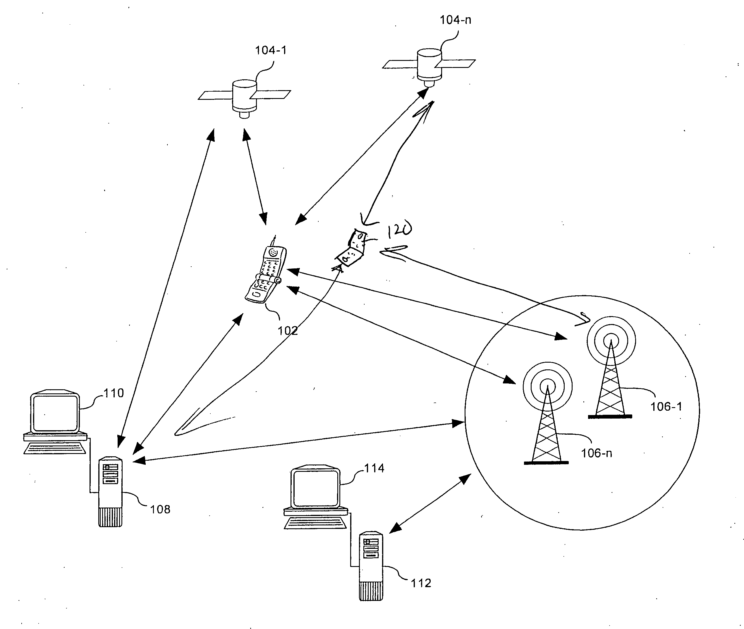
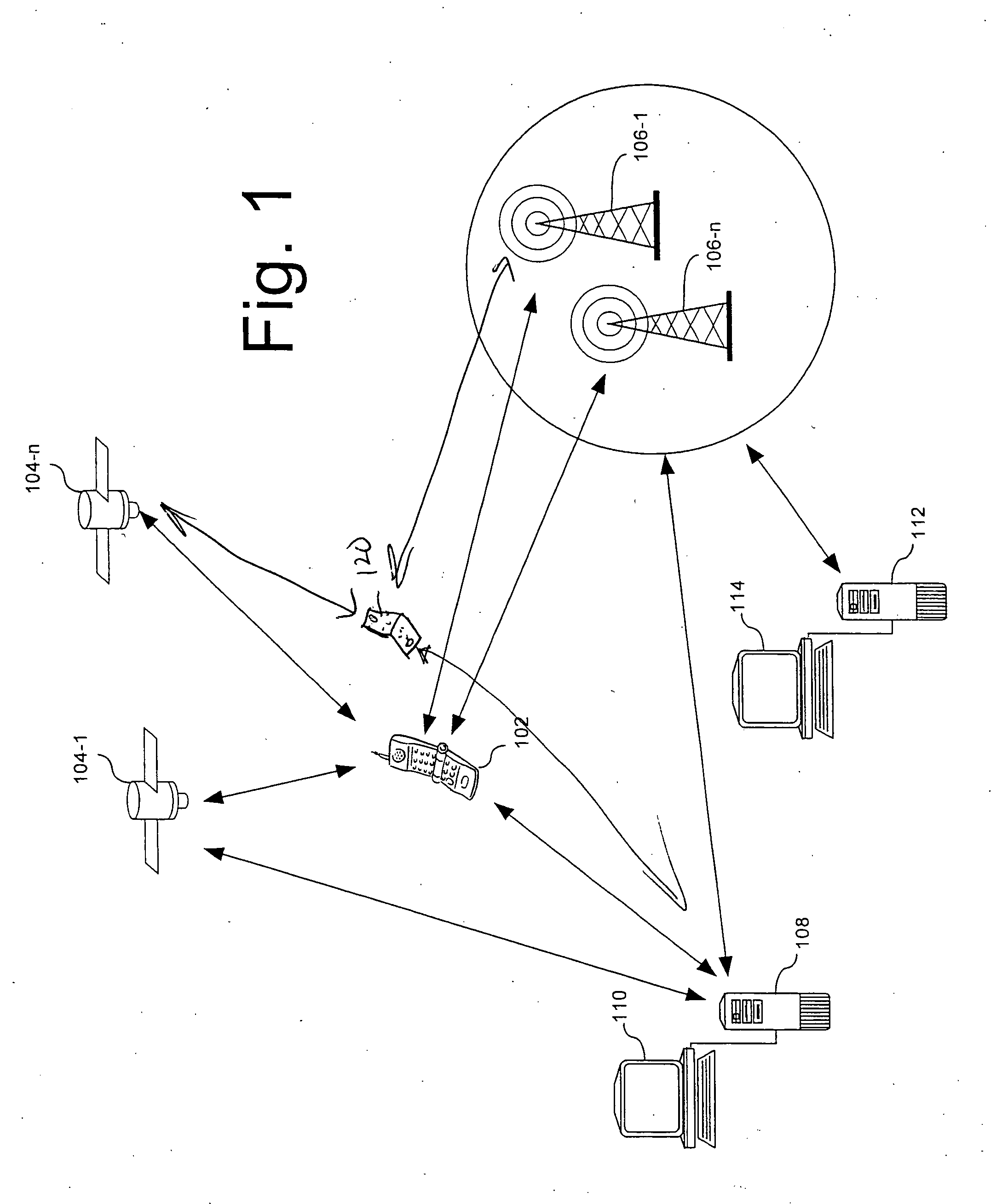
[0023]FIG. 1 is a drawing that is useful for understanding the operation of a wireless automatic location identification system in accordance with the inventive arrangements. As illustrated therein, an automatic location identification (ALI) system can rely on a combination of both network based and GPS based solutions. Such systems collect GPS measurements and network measurements and send the measurement data to the position determination entity. A server can then process the measurements to produce the most accurate location information based on available data.

[0024] More particularly, FIG. 1 shows that a conventional network based ALI solution can automatically identify a physical location of a wireless device 102 or 120 by measuring angle of arrival (AOA) and time of arrival (TOA) of cell phone signals at multiple fixed base stations 106-1, 106-n. The wireless device 102 can be a wireless PDA, cell phone, laptop computer, or any other device incorporating suitable processing a...


PUM


Abstract

The invention concerns a method for identifying a physical meeting location using an automatic location identification (ALI) equipped wireless device. The method can include the steps of identifying a first physical location of a remote ALI equipped wireless device; calculating a second physical location corresponding to a location of the wireless device; and displaying on said wireless device at least one a bearing and distance from said first physical location to said second physical location. The invention can also include the step of processing the data to identify a third physical location between the first and second physical locations; and displaying on the wireless device information concerning at least the third physical location.

Description

CROSS-REFERENCE TO RELATED APPLICATIONS [0001] This Application is a Non-Provisional of Provisional (35 USC 119(e)) application 60 / 553,242 filed on Mar. 15, 2004.BACKGROUND OF THE INVENTION [0002] The inventive arrangements relate generally to wireless devices and more particularly to wireless devices with automatic location identification capabilities for determining a convenient meeting place between two locations. [0003] In June 1996, the Federal Communications Commission (FCC) set in place a two-phase plan for implementing wireless 911 in the United States. Phase I, which was originally to have been implemented by April 1998, required callback numbers and cell site sector information about each incoming wireless 911 call. Cell phones that met the Phase I requirements provided a general indication of the caller's location, although the area may be as large as 100 square miles. [0004] Phase II, which was originally scheduled to have been implemented by October 2001, required wirel...

Claims


Application Information

Patent Timeline
IPC IPC(8): H04W4/21
CPCH04W4/206H04W4/023H04W4/21
Inventor SUDIT, ISAIAS
Owner LOC AID TECH
Why Eureka
Try Eureka