
Apparatus for controlling the position of a screen pointer with low sensitivity to particle contamination

a technology of particle contamination and a display screen, applied in the direction of electrical digital data processing, structural/machine measurement, instruments, etc., can solve the problems of inaccurate sensor values, defective pixels can also arise, and digital image sensors often contain a few defective pixels, so as to achieve low sensitivity to effects

Active Publication Date: 2005-09-22
PIXART IMAGING INC
View PDF22 Cites 26 Cited by
  • Summary
  • Abstract
  • Description
  • Claims
  • Application Information

AI Technical Summary

Benefits of technology

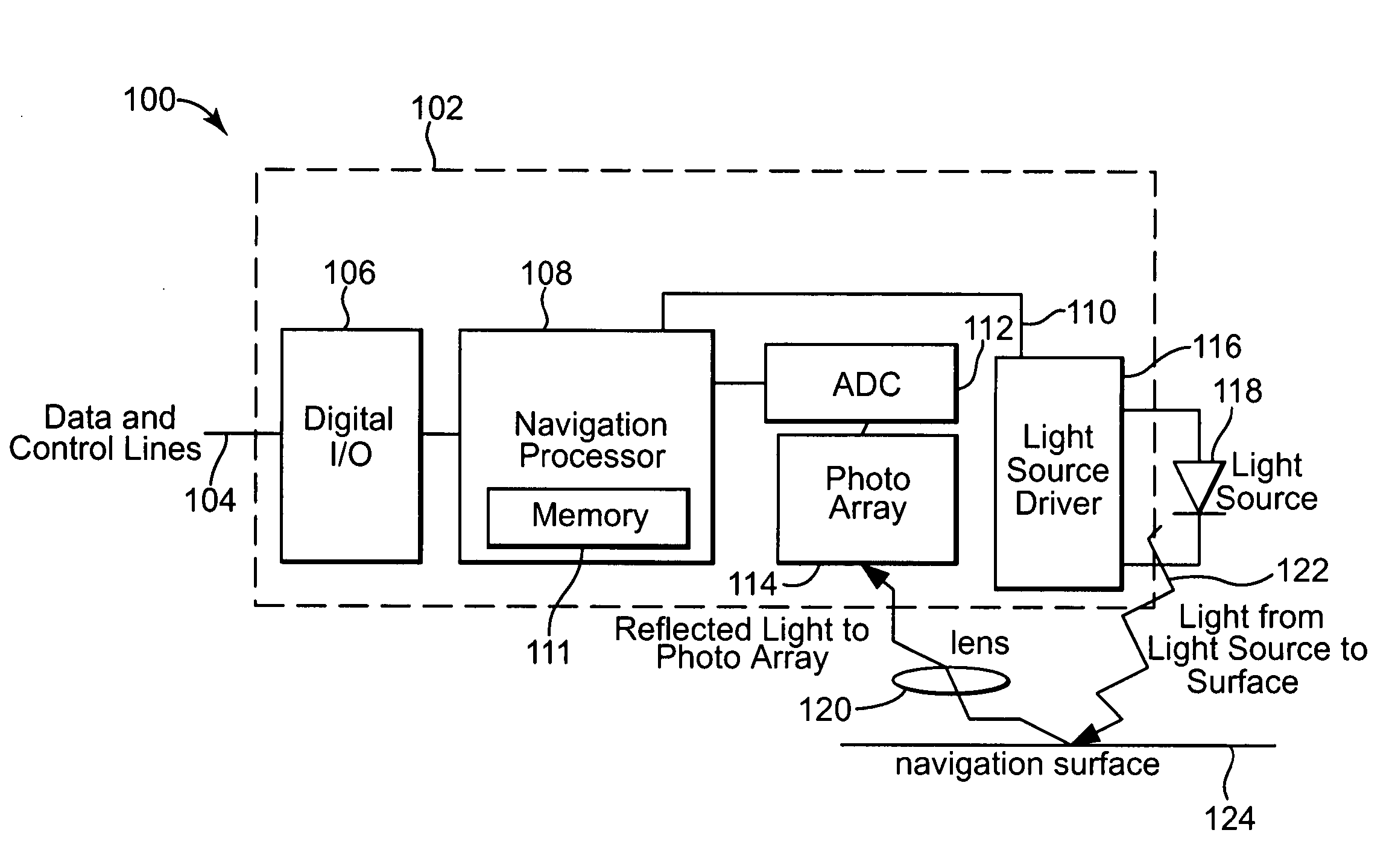
[0009] One form of the present invention provides an apparatus for controlling the position of a screen pointer. The apparatus includes an at least partially coherent light source for illuminating an imaging surface, thereby generating reflected images. The apparatus includes a navigation sensor for generating digital images based on the ref

Problems solved by technology

Despite advances in the manufacturing process, digital image sensors often contain a few defective pixels as a result of noise or fabrication errors, such as impurity contamination.
Defective pixels can also arise after the manufacturing process and during use by a customer.
Defective pixels respond inappropriately to the incident light, and therefore produce inaccurate sensor values.
If the image sensor of an optical pointing device contains defective pixels, such as stuck high or stuck low pixels, the values from these pixels may never change, which biases the navigation computation and can cause errors.
The values from abnormal sensitivity pixels may change, but such pixels do not perform as expected and can also cause errors.
The bad pixels can be caused by one or more of the following: (1) defects in the silicon; (2) external contamination (e.g., particles such as dust or dirt, fibers, “flash,” etc., landing on the array); and (3) improper illumination (e.g., the illumination spot can be de-centered such that part of the array is too “dark”).
“Flash” is mold compound that sticks out from a molded piece and that can come loose from the molded piece during production or during use by a customer, and cause particle contamination of the array.
For optical pointing devices that use incoherent illumination, such as typical LED-based devices, dust and other particle contamination may remain out of focus and, therefore, have a negligible effect on performance.
Coherent illumination of dust particles and other particle contamination can produce visible fringe artifacts in the generated images, which adversely affects performance.
It is difficult to completely eliminate particle contamination in optical pointing devices.

Method used


Image

  • Apparatus for controlling the position of a screen pointer with low sensitivity to particle contamination
  • Apparatus for controlling the position of a screen pointer with low sensitivity to particle contamination
  • Apparatus for controlling the position of a screen pointer with low sensitivity to particle contamination

Examples


Embodiment Construction

[0017] In the following detailed description of the preferred embodiments, reference is made to the accompanying drawings, which form a part hereof, and in which is shown by way of illustration specific embodiments in which the invention may be practiced. It is to be understood that other embodiments may be utilized and structural or logical changes may be made without departing from the scope of the present invention. The following detailed description, therefore, is not to be taken in a limiting sense, and the scope of the present invention is defined by the appended claims.

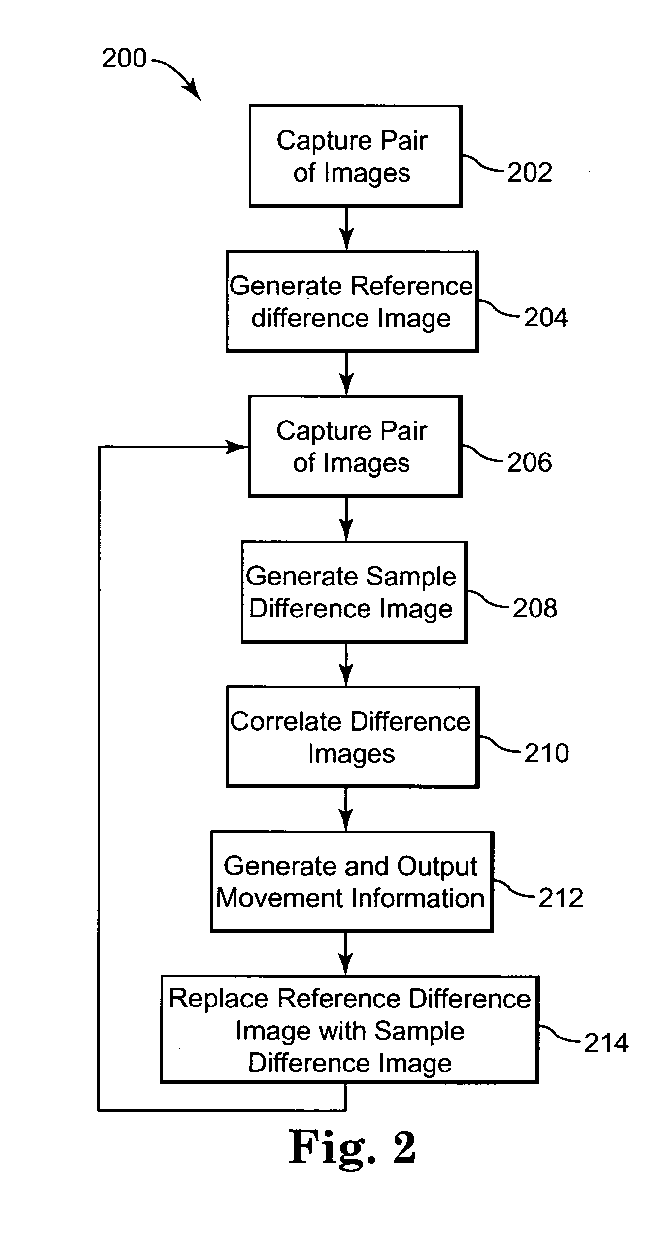
[0018] As mentioned above in the Background of the Invention section, particle contamination can adversely affect the performance of optical pointing devices that use coherent illumination. It is difficult to completely eliminate particle contamination in these optical pointing devices. Thus, one form of the present invention provides a compensation mechanism to cope with dust or other particle contamination b...


PUM


Abstract

An apparatus for controlling the position of a screen pointer includes an at least partially coherent light source for illuminating an imaging surface, thereby generating reflected images. The apparatus includes a navigation sensor for generating digital images based on the reflected images, performing a movement computation based on the digital images, generating movement data based on the movement computation that is indicative of relative motion between the imaging surface and the apparatus, wherein the movement computation has a low sensitivity to effects in the digital images caused by particle contamination.

Description

CROSS-REFERENCE TO RELATED APPLICATIONS [0001] This application is related to U.S. patent application Ser. No. ______, attorney docket no. 10040077-1, filed Mar. 8, 2004, and entitled APPARATUS FOR CONTROLLING THE POSITION OF A SCREEN POINTER THAT DETECTS DEFECTIVE PIXELS; and U.S. patent application Ser. No. ______, attorney docket no. 10040349-1, filed on the same date as the present application, and entitled CONTAMINANT-RESISTANT OPTICAL MOUSE AND CRADLE.THE FIELD OF THE INVENTION [0002] This invention relates generally to devices for controlling a pointer on a display screen, and relates more particularly to an apparatus for controlling the position of a screen pointer with low sensitivity to particle contamination. BACKGROUND OF THE INVENTION [0003] The use of a hand operated pointing device for use with a computer and its display has become almost universal. One form of the various types of pointing devices is the conventional (mechanical) mouse, used in conjunction with a coo...

Claims


Application Information

Patent Timeline
IPC IPC(8): G06F3/042G06F3/03G06F3/041G06K11/06G09G5/00
CPCG06F3/0317G01M11/00
Inventor BROSNAN, MICHAEL J.KAKARALA, RAMAKRISHNAGREWAL, ROOPINDER SINGHBUTTERWORTH, MARK M.MOYER, VINCENT C.XIE, TONGDEPUE, MARSHALL T.
Owner PIXART IMAGING INC
Learn More