Method and circuit for detecting flicker noise

a technology of flicker noise and detection method, applied in the field of methods can solve the problems of flicker noise produced under different conditions, and achieve the effect of reducing the time for detecting flicker nois

Inactive Publication Date: 2005-09-22
SOCIONEXT INC
View PDF7 Cites 19 Cited by
  • Summary
  • Abstract
  • Description
  • Claims
  • Application Information

AI Technical Summary

Benefits of technology

[0038] The present invention provides a method for detecting flicker noise that reduces the time for detecting flicker noise.
[0039] Further, the present inv

Problems solved by technology

Thus, flicker noise is produc

Method used


Image

  • Method and circuit for detecting flicker noise
  • Method and circuit for detecting flicker noise
  • Method and circuit for detecting flicker noise

Examples


Embodiment Construction

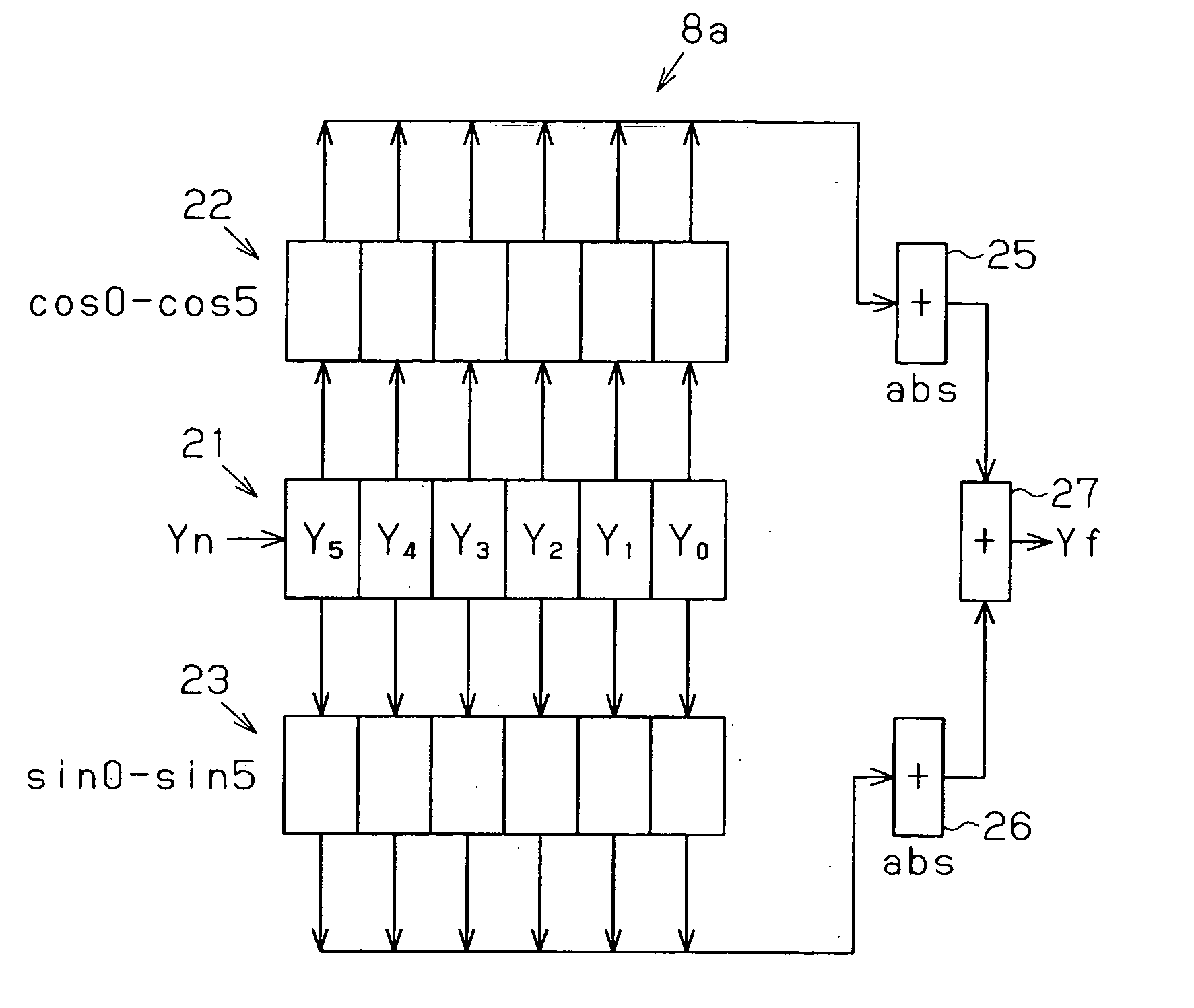
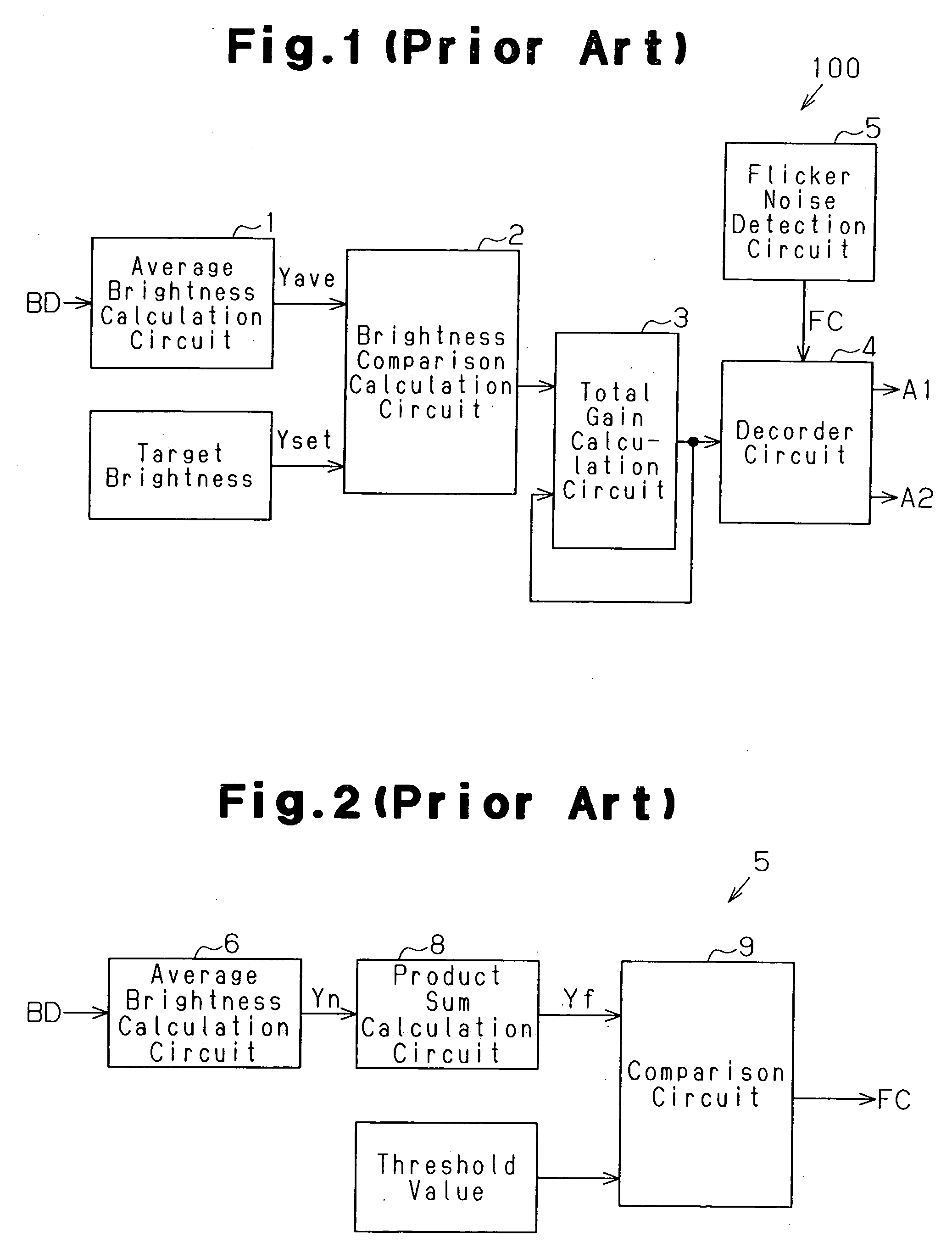
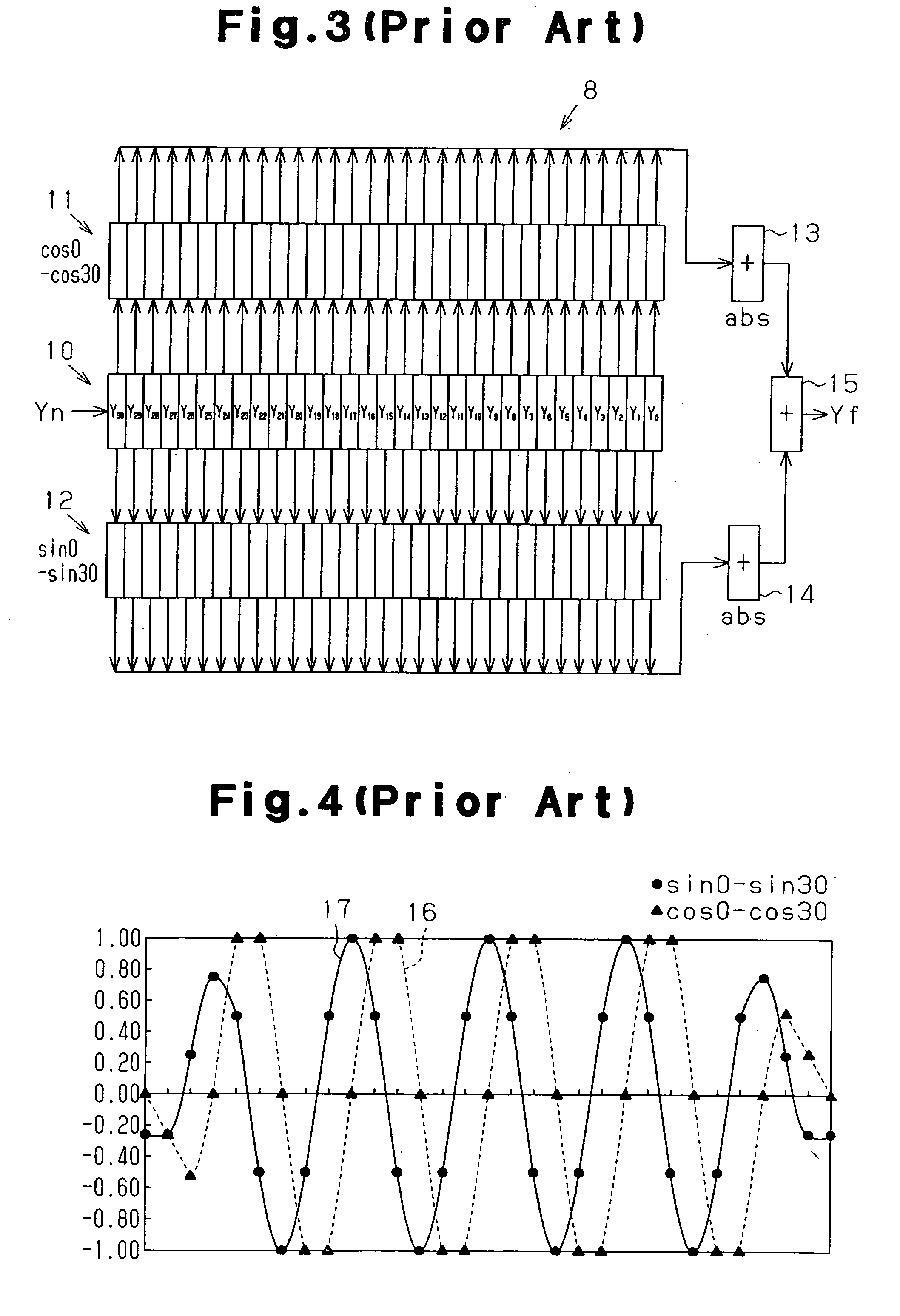
[0068] An AGC circuit according to a preferred embodiment of the present invention will now be discussed. In the preferred embodiment, the selection of the integration time based on the integration time adjustment signal A2 output from the decoder circuit 4 during the detection of flicker noise and the configuration of the product sum calculation circuit 8 of the flicker noise detection circuit 5 are modified from the AGC circuit 100 shown in FIG. 1. The prior art AGC circuit 100 of FIG. 1 and the flicker noise detection circuit 5 of FIG. 2 function in the same manner as the AGC circuit and flicker noise detection circuit of the preferred embodiment except for the product sum calculation circuit 8 and the decoder circuit 4. Accordingly, in drawings showing the preferred embodiment, parts corresponding to those of the prior art are denoted with the same reference numbers except for a product sum calculation circuit 8a, which is shown in FIG. 7.

[0069] Referring to FIG. 7, in the pref...


PUM


Abstract

A flicker noise detecting method that shortens the time for detecting flicker noise. The method sets two of a plurality of horizontal lines forming a frame as average brightness calculation regions that are separated from each other by the predetermined number of the horizontal lines, calculates an average brightness of the two average brightness calculation regions for each of three frames, multiplies each average brightness by a product sum calculation coefficient, and adds the products to generate a sum and generate a detection signal of flicker noise based on the sum. The product sum calculation coefficient is obtained by plotting one cycle of a sine wave and one cycle of a cosine wave at intervals of π/3.

Description

CROSS-REFERENCE TO RELATED APPLICATIONS [0001] This application is based upon and claims the benefit of priority from prior Japanese Patent Application No. 2004-076908, filed on Mar. 17, 2004, the entire contents of which are incorporated herein by reference. BACKGROUND OF THE INVENTION [0002] The present invention relates to a method for detecting flicker noise, and more particularly, to a method for detecting flicker noise produced when generating an image with an imaging device, such as a digital still camera or a digital video camera, indoors near a fluorescent light. [0003] A fluorescent light may be used as a lighting device in a room. In such a room, when an imaging device, such as a digital still camera or a digital video camera, is used to generate an image, the generated image may include flicker noise in accordance with the relationship between the exposure time of photoelectric conversion elements, which configure an image sensor, and the fluorescence frequency of the fl...

Claims


Application Information

Patent Timeline
IPC IPC(8): H04N5/235H04N5/21H04N5/243H04N9/73H04N17/00H04N101/00
CPCH04N5/2357H04N17/002H04N5/243H04N23/745H04N23/76
Inventor DAIKU, HIROSHIKOKUBO, ASAO
Owner SOCIONEXT INC
Why Eureka
Try Eureka