Wall mountable laser level

a laser level and laser level technology, applied in the field of laser leveling instruments, can solve the problems of chalk line imprinting on walls, cumbersome alignment products, impracticality,

Active Publication Date: 2005-09-22
IDEAVILLAGE PRODS
View PDF2 Cites 31 Cited by
  • Summary
  • Abstract
  • Description
  • Claims
  • Application Information

AI Technical Summary

Benefits of technology

[0010] According to a first aspect of the invention, a laser level is adapted to direct a laser path against a working surface. The level comprises a base, the base comprising at least one pair of opposing edges, the base adapted to be positioned relative to the working surface such that each of the opposing edges is adjacent to the working surface. The level comprises an adhesive layer, the adhesive layer being situated on the base so as to removably affix the base on the working surface without damaging the working surface. The level comprising an activating switch, the switch being located on the level at a location offset from the laser path.
[0027] According to a further aspect of the invention, the level further comprises an adhesive layer, the adhesive layer being adjacent to the base for removably attaching the base to the working surface without damaging the working surface.

Problems solved by technology

Some of these alignment products are cumbersome, others are impractical.
However, chalk lines leave imprints on walls and produce chalk dust, both of which are undesirable in a finished room.
The Malard device has several problems.
A first problem concerns the way the laser is activated.
A second problem with the Malard device concerns the method in which the laser apparatus connects to a solid surface.
In use, the pin damages the surface being connected to the apparatus.
However, the Command Strips contain deficiencies.
Accordingly, the Command Strips have problems inherent with suction-cups.
If the receiving surface contains any irregularities, the porous opening will fail to grip and the Malard apparatus will fail to adhere to the surface.
However, such irregularities are common to surfaces on which the laser is be applied, such as with textured paint or various forms of wall board or wall paper.
Another problem exists when applying the Command Strips against the base of the Malard device.
The displaced device is caused to wobble against the surface due to the compressibility of the strips.
The wobbling is incurable because edges of the base are incapable of contacting the working surface due to the strips.

Method used


Image

  • Wall mountable laser level
  • Wall mountable laser level
  • Wall mountable laser level

Examples


Embodiment Construction

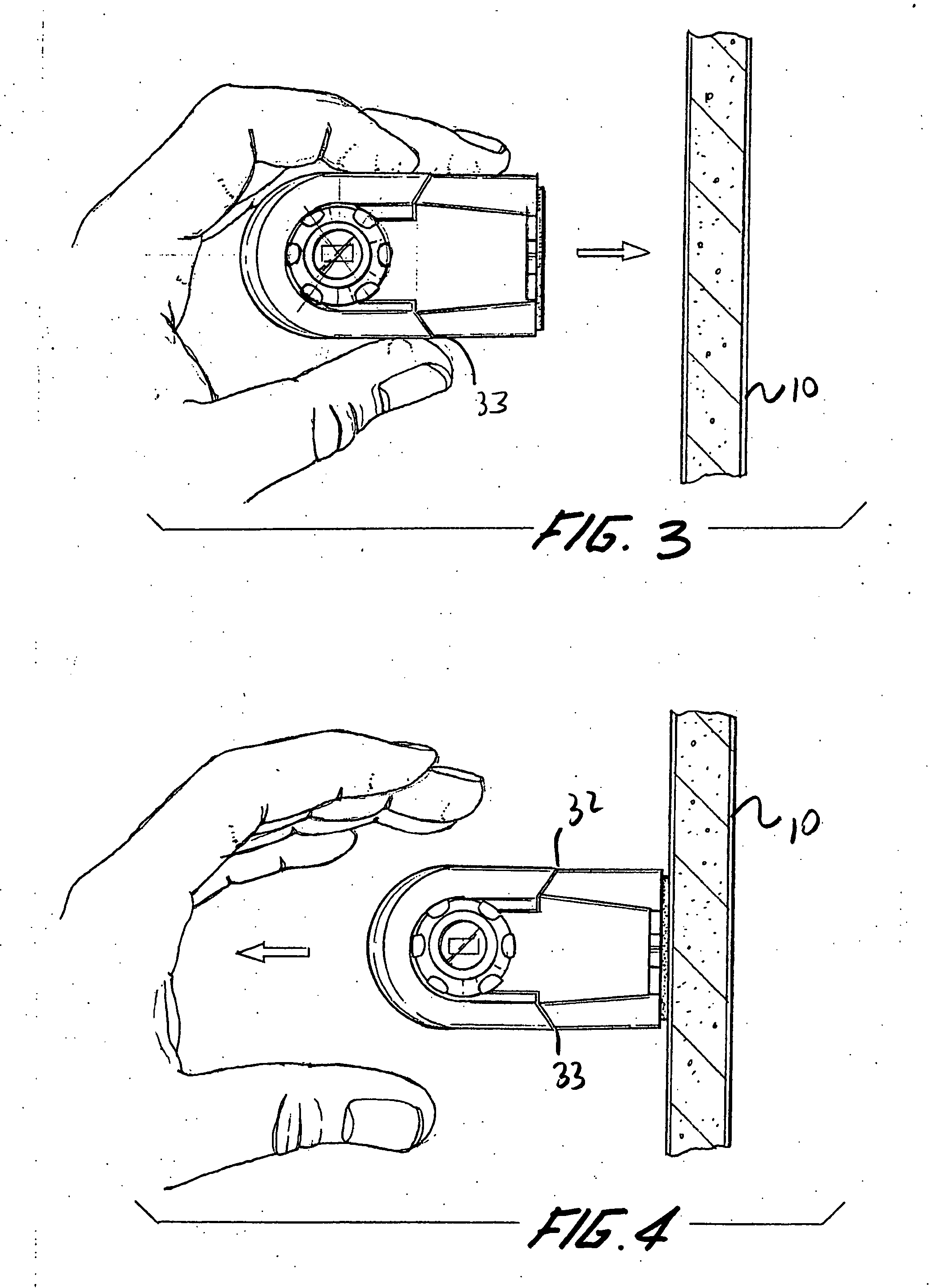
[0039] A laser level is disclosed that utilizes an adhesive for adhering to a working surface. The level has recessed base for placement of the adhesive, and where edges of the recess are capable of maintaining contact with the working surface during the use of the adhesive. The level provides a comfortable gripping surface that helps to prevent the user from pinching fingers against the working surface. The level is capable of being operated without exposing the user's fingers to the laser beam.

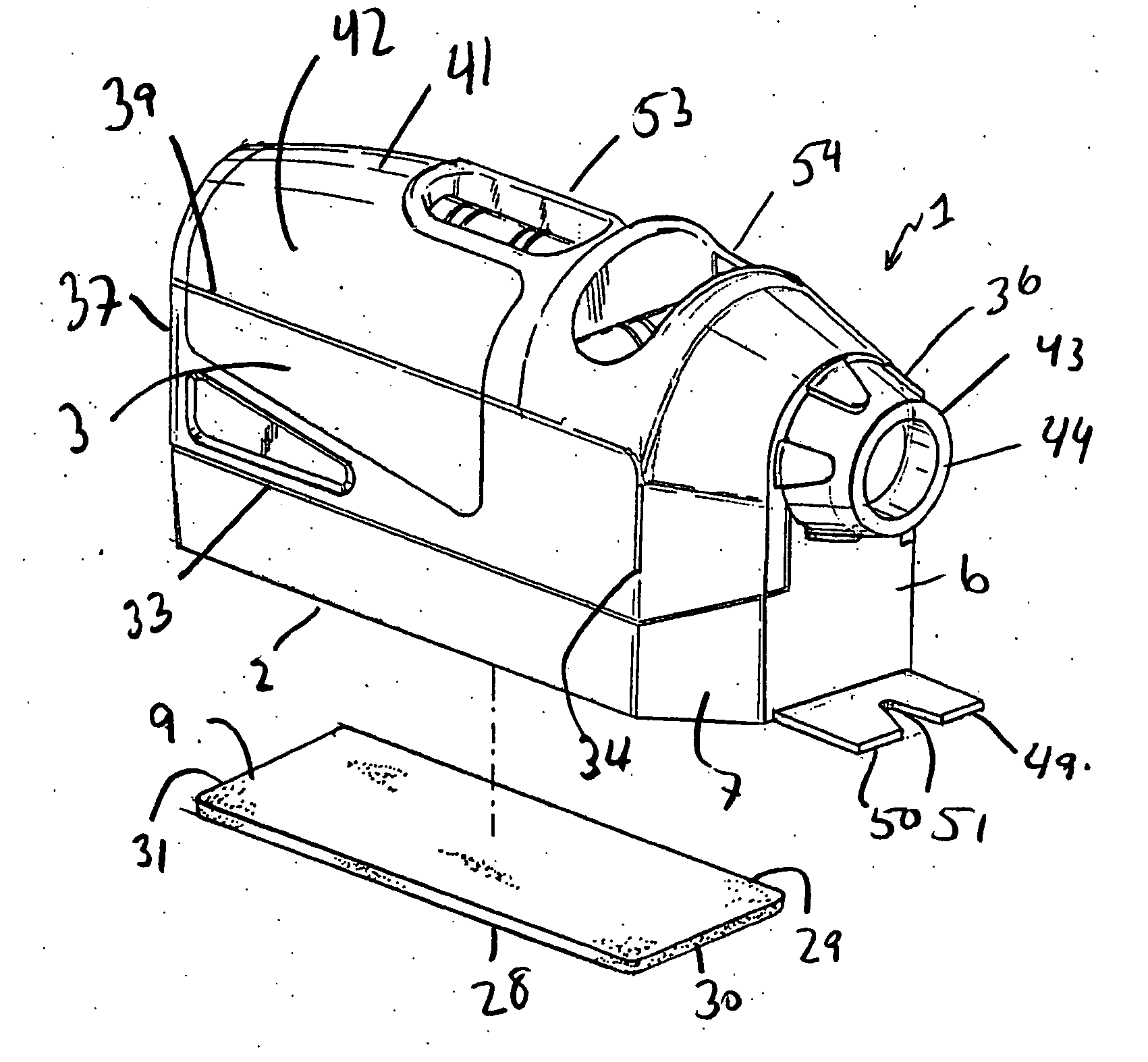
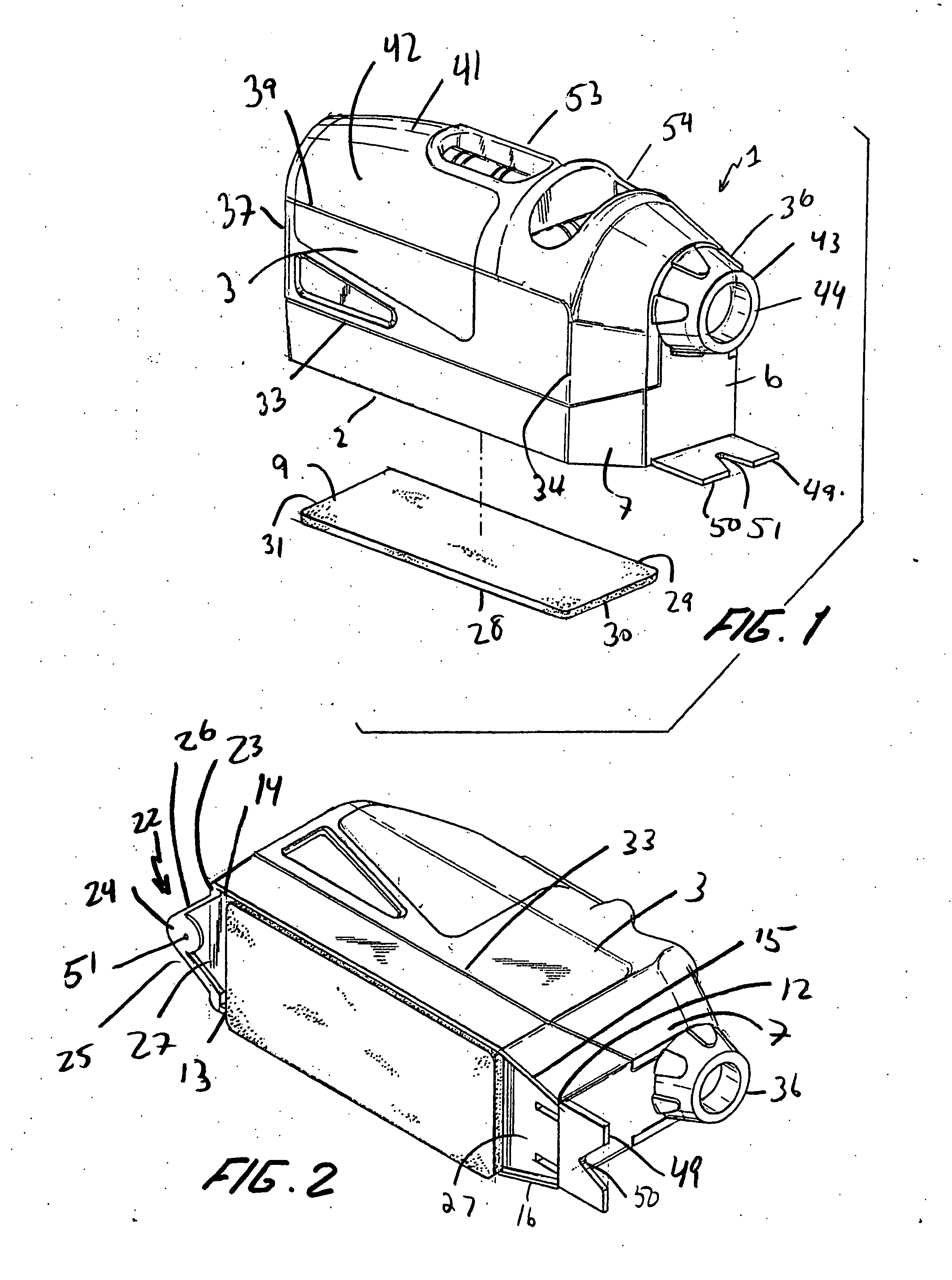
[0040] Turning to the FIG. 1, to better understand the invention, there is disclosed a laser level 1 having body segments for storing the internal components. The body segments include a base 2, sides 3 and 4 (FIG. 7) perpendicular to the base, and back 5 (FIG. 6) and front 6, both being perpendicular to sides 3 and 4. The level 1 also has surfaces 7 and 8 which join surfaces 3 and 4 to front 6. The level 1 has adhesive tape 9 for connecting the level to a working surface 10 (FIG. 3). The l...


PUM


Abstract

A laser level is adapted to direct a laser path against a working surface. The level comprises a base, the base comprising at least one pair of opposing edges, the base adapted to be positioned relative to the working surface such that each of the opposing edges is adjacent to the working surface. The level comprises an adhesive layer, the adhesive layer being situated on the base so as to removably affix the base on the working surface without damaging the working surface. The level comprising an activating switch, the switch being located on the level at a location offset from the laser path.

Description

FIELD OF THE INVENTION [0001] The present invention relates generally to laser leveling instruments, and more particularly to a wall mountable laser level. BACKGROUND OF THE INVENTION [0002] Alignment of surfaces is a concern in a variety of fields, ranging from construction to interior decorating. Alignment is necessary for walls that should be perpendicular to a floor, or otherwise plumb. Vertical or horizontal alignment is especially important for pictures and other wall ornamentation. [0003] Many mechanical alignment devices are available. Some of these alignment products are cumbersome, others are impractical. Chalk reels, for instance, are readily portable and create reliable alignment markings. However, chalk lines leave imprints on walls and produce chalk dust, both of which are undesirable in a finished room. Plumb bobs are also readily portable, but require anchoring of a string and the bob must come to rest before being relied upon for alignment purposes. [0004] The probl...

Claims


Application Information

Patent Timeline
Patent Type & Authority Applications(United States)
IPC IPC(8): G01C9/18G01C15/00
CPCG01C15/008
Inventor KHUBANI, ANAND
Owner IDEAVILLAGE PRODS
Why Eureka
Try Eureka