Methods and apparatus to reduce blocking noise and contouring effect in motion compensated compressed video

a compression video and video signal technology, applied in the field of methods and systems for removing blocking artifacts and contouring effects found in blockencoded video signals, can solve the problems of inability to reduce noise at the center region of the block, block effect, and inability to reduce nois

Inactive Publication Date: 2005-09-22
SONY CORP +1
View PDF12 Cites 94 Cited by
  • Summary
  • Abstract
  • Description
  • Claims
  • Application Information

AI Technical Summary

Problems solved by technology

The blocking effect is a particular problem along edges or color boundaries in the image or in areas of the image that are of relatively uniform color.
Generally, in a low bit-rate case, the blocking noise will occur at the block boundaries and the motion compensation scheme will make things worse by propagating the blocking noise to the following predicted frames.
These techniques can reduce the blocking noise near the block boundary, but fail to reduce the noise at the center region of the block.
After motion compensation, the noise at the boundary from the previous frame is moved to the center of the block and existing de-blocking techniques fail to detect this situation and noise is unable to be reduced.
The implementation of the de-blocking filter as shown in FIG. 1 is not normative in the MPEG-1,2,4 standard, because system has the tendency to have high computation requirement or be unsuccessful in reducing the noise at the center region of a block.
However, most of the filters are implemented only to check the pixels close to the block boundary 32, which will fail to reduce the noise caused by the noise propagated by motion compensation.
The boundaries of these constant pixel regions are called “contours,” and are generally annoying to the human visual system.

Method used


Image

  • Methods and apparatus to reduce blocking noise and contouring effect in motion compensated compressed video
  • Methods and apparatus to reduce blocking noise and contouring effect in motion compensated compressed video
  • Methods and apparatus to reduce blocking noise and contouring effect in motion compensated compressed video

Examples


Embodiment Construction

[0052] Referring more specifically to the drawings, for illustrative purposes the present invention is embodied in the systems and methods generally shown in FIG. 4 through FIG. 12. It will be appreciated that the methods may vary as to configuration and as to details of the parts, and that the methods may vary as to the specific steps and sequence, without departing from the basic concepts as disclosed herein.

[0053] 1. Reduction of Blocking Noise

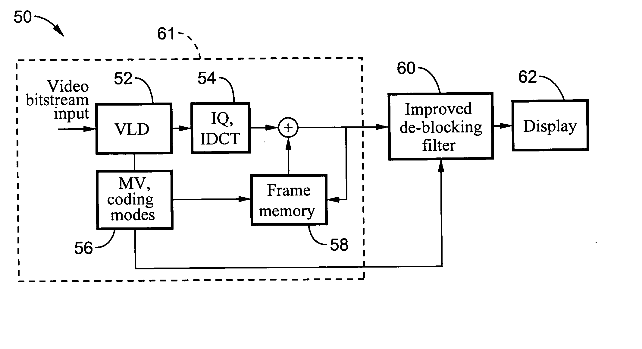
[0054]FIGS. 4 through 7 illustrate a simple but effective system and method for reducing the blocking noise regardless the noise location. It has been recognized that the undesirable blocking noise at the center region of a block in a predicted frame is caused by motion compensation. The disclosed system and methods reduce the noise by tracking the motion vector information for the block. As a result, the artifact introduced by the noise from the reference frame and motion compensation can be reduced.

[0055] The reason for the blocking no...


PUM


Abstract

A method and systems are disclosed for removing artifacts, such as blocking noise and contouring effects, from a block-encoded video signal. One method for removing blocking artifacts comprises decoding the block-encoded signal to obtain a decoded sequence of video frames and one or more associated motion vectors. By using the motion vector, the location of one or more blocking artifacts may be identified within at least one of the frames. The location identified by the motion vector is filtered to remove at least some of the blocking artifacts. Another method for removing contouring effects comprises decoding the block-encoded signal to obtain a decoded sequence of video frames, detecting a contouring effect by evaluating the macroblock mode and DCT coefficient information from the decoded signal, and filtering one or more blocks correlating to the detected contouring effect.

Description

CROSS-REFERENCE TO RELATED APPLICATIONS [0001] This application claims priority from U.S. provisional application Ser. No. 60 / 554,530 filed on Mar. 18, 2004, incorporated herein by reference in its entirety.STATEMENT REGARDING FEDERALLY SPONSORED RESEARCH OR DEVELOPMENT [0002] Not Applicable INCORPORATION-BY-REFERENCE OF MATERIAL SUBMITTED ON A COMPACT DISC [0003] Not Applicable NOTICE OF MATERIAL SUBJECT TO COPYRIGHT PROTECTION [0004] A portion of the material in this patent document is subject to copyright protection under the copyright laws of the United States and of other countries. The owner of the copyright rights has no objection to the facsimile reproduction by anyone of the patent document or the patent disclosure, as it appears in the United States Patent and Trademark Office publicly available file or records, but otherwise reserves all copyright rights whatsoever. The copyright owner does not hereby waive any of its rights to have this patent document maintained in secr...

Claims


Application Information

Patent Timeline
Patent Type & Authority Applications(United States)
IPC IPC(8): H04N7/12H04N7/26H04N7/50
CPCH04N19/139H04N19/61H04N19/86H04N19/157H04N19/117
Inventor PAO, I-MING
Owner SONY CORP
Why Eureka
Try Eureka