Surface replacement extractor device and associated method

a surface replacement and extractor technology, applied in the field of orthopaedics, can solve the problems of limiting the load transfer capability between the prosthesis and the humerus, the need to remove, and the flattening of the humeral head

Active Publication Date: 2005-09-22
DEPUY PROD INC
View PDF99 Cites 141 Cited by
  • Summary
  • Abstract
  • Description
  • Claims
  • Application Information

AI Technical Summary

Benefits of technology

[0025] Another technical advantage of the present invention includes the ability of the instrument to be used with one hand. For example, according to another aspect of the present invention the first and second members are lockably engaged with the implant and a distal handle is provided. Thus the present invention provides for the use of the tool with one hand.
[0026] Another technical advantage of the present invention is the ability of the instrument to be used with a mallet. For example, according to one aspect of the present invention the instrument includes a surface for receiving strikes with a mallet. Further the instrument may include a cylindrical shaft portion for engagement with a slotted mallet. Thus the present invention provides for an instrument that may be used with a mallet.
[0027] Technical advantages of the present inventions further include the ability to permit the removal of the initial implant to perform revisions of the stem implant. For example, according to one aspect of the present invention, the instrument includes a first member and a second member for engaging the implant and to permit the removal of an implant in the axial direction. Thus the present invention provides for the removal of the initial implant to perform revisions to the stem implant.

Problems solved by technology

Typically, however, arthritis of the gleno-humeral joint causes flattening of the humeral head with a large medial osteophyte.
The flat humeral head can cause voids in the bone under the prosthesis resulting in limited contact between the prosthesis and the resected bone and may limit the load transfer capability between the prosthesis and the humerus.
During a surface replacement procedure, it may be necessary to remove the initial implant once seated because of incorrect sizing.
Prior art attempts at removing the implant have resulted in the damage of the surrounding bone during the removal of the implant.
Extraction of the initial implant may be made more difficult if the initial implant includes a porous coating to promote bony in-growth.
The bony in-growth of the surface implant stem may make the removal of the surface replacement prosthesis extremely difficult.
Prior art procedures for the removal of the surface replacement prostheses have been limited to the use of an osteotome and a mallet to wedge the implant from under the outer lip of the implant and free the implant from the bone underneath the implant.
The removal of the implant from the bone using an osteotome and a wedge is wrought with many problems including damage to the bone around the implant and generally difficulty in removal of the implant.

Method used


Image

  • Surface replacement extractor device and associated method
  • Surface replacement extractor device and associated method
  • Surface replacement extractor device and associated method

Examples


Embodiment Construction

[0056] Embodiments of the present invention and the advantages thereof are best understood by referring to the following descriptions and drawings, wherein like numerals are used for like and corresponding parts of the drawings

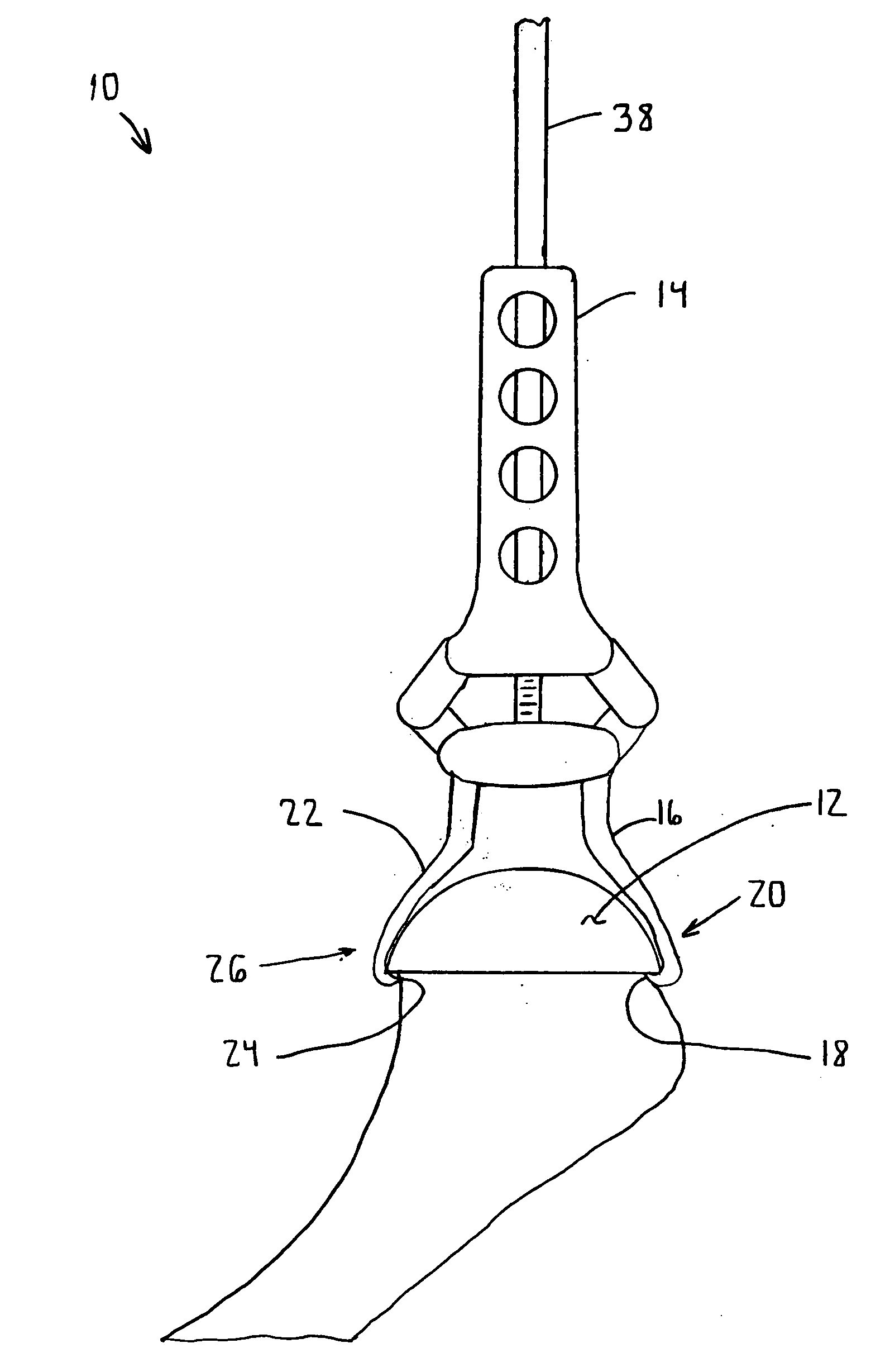
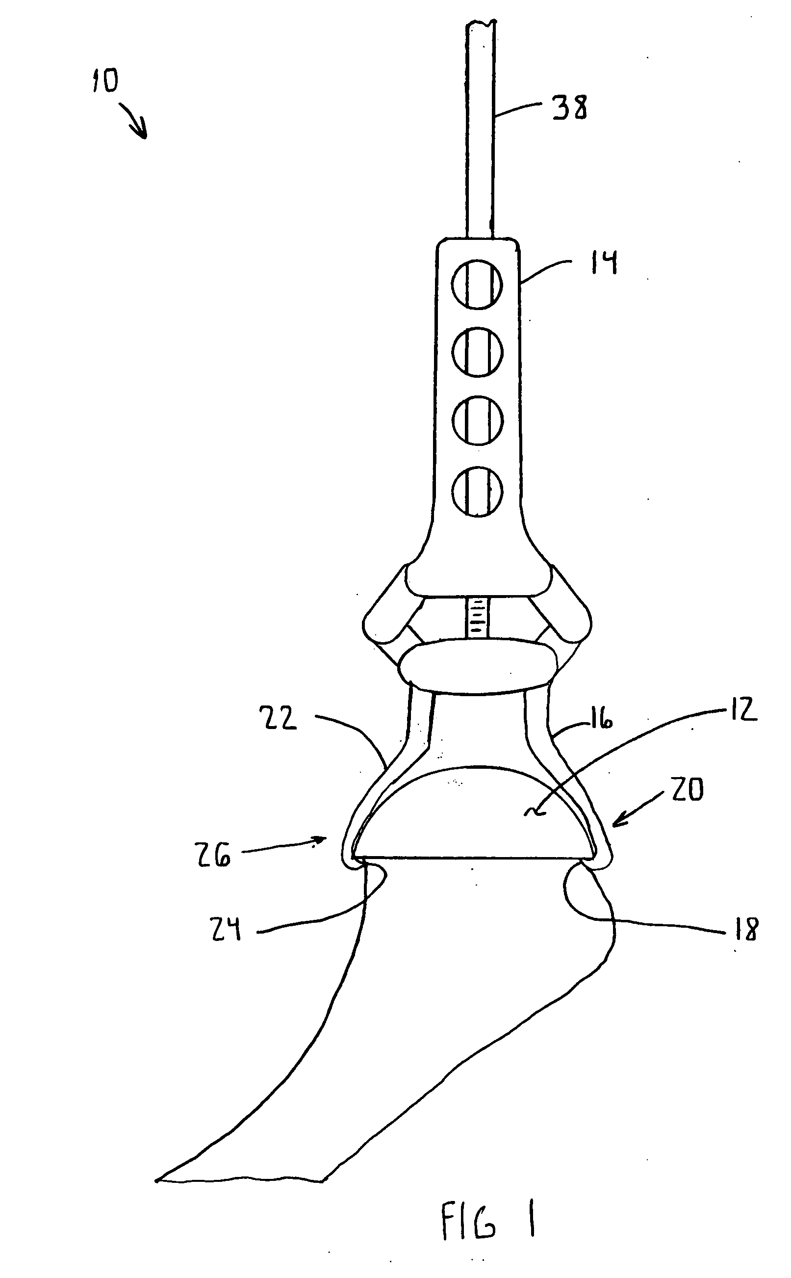
[0057] According to the present invention and referring now to FIG. 1, an instrument 10 is shown for use in removal of a prosthesis implant, for example, conservative humeral implant 12 for use in performing arthoplasty. The instrument 10 includes a body 14 and a first member 16. The first member 16 is operably associated with the body 14. The first member 16 includes a contact portion 18 for engagement with the implant 12 at the first position 20.

[0058] The instrument 10 further includes a second member 22. The second member 22 is operably associated with the body 14. The second member 22 is movable to respect to the first member 16. The second member 22 includes a contact portion 24 for engaged with the implant 12 at a second position 26 spaced from the fi...


PUM


Abstract

An instrument for use in removal of a prosthetic implant for use performing arthroplasty is provided. The instrument includes a body and a first member. The first member is operably associated with the body. The first member has a contact portion for engagement with the implant at a first position. The instrument also includes a second member operably associated with the body. The second member is moveable with respect to the first member and the second member has a contact portion for engagement with the implant at a second position, spaced from the first position.

Description

CROSS-REFERENCE TO RELATED APPLICATIONS [0001] Cross reference is made to the following applications: U.S. patent application Ser. No. 10 / 403,707 filed Mar. 31, 2003, entitled “ARTHROPLASTY SIZING GAUGE”, U.S. patent application Ser. No. 10 / 403,750 filed Mar. 31, 2003, entitled “ARTICULATING SURFACE REPLACEMENT PROSTHESIS”, U.S. patent application Ser. No. 10 / 403,577 filed Mar. 31, 2003, entitled “MODULAR ARTICULATING SURFACE REPLACEMENT PROSTHESIS”, U.S. patent application Ser. No. 10 / 403,710 filed Mar. 31, 2003, entitled “ARTHROPLASTY INSTRUMENT AND ASSOCIATED METHOD”, U.S. patent application Ser. No. 10 / 403,708 filed Mar. 31, 2003, entitled “EXTENDED ARTICULATION ORTHOPAEDIC IMPLANT AND ASSOCIATED METHOD” and U.S. patent application Ser. No. 10 / 403,364 filed Mar. 31, 2003, entitled ““PROSTHETIC IMPLANT, TRIAL AND ASSOCIATED METHOD” which are incorporated herein by reference in their entities.TECHNICAL FIELD OF THE INVENTION [0002] The present invention relates generally to the fi...

Claims


Application Information

Patent Timeline
Patent Type & Authority Applications(United States)
IPC IPC(8): A61F2/00A61F2/34A61F2/36A61F2/46
CPCA61F2/34A61F2002/4628A61F2/4607A61F2/4609A61F2002/30411A61F2002/30428A61F2002/30471A61F2002/30507A61F2002/4619A61F2002/4622A61F2002/4681A61F2220/0025A61F2220/0091A61F2002/4627A61F2/3603
Inventor LONG, JACK F.VONZABERN, ROBERT
Owner DEPUY PROD INC
Why Eureka
Try Eureka