Electronic metronome and method of indicating tempo of electronic metronome

a technology of electronic metronome and tempo, which is applied in the direction of preselected time interval producing apparatus, instruments, music, etc., can solve the problem that the user may feel discomfort in keeping up with the tempo

Inactive Publication Date: 2005-09-29
SEIKO INSTR INC
View PDF10 Cites 7 Cited by
  • Summary
  • Abstract
  • Description
  • Claims
  • Application Information

AI Technical Summary

Benefits of technology

[0006] It is an object of the present invention to provide an electronic metronome employing a tempo indicating method more similar to that of a mechanical metronome by making a display reproducing a movement of a baton of the mechanical metronome as a reciprocating lighting-up movement of a plurality of light emitting elements and slightly offsetting a timing for emitting a sound for the display from either terminal one of the light emitting elements or segments.
[0007] To achieve the above object, an electronic metronome of the present invention includes a timing setting portion for setting a timing for emitting a sound, a control portion that outputs pieces of tempo indication data and a tempo sound signal, which are based on a piece of data on a set tempo, respectively at timings based on a piece of sound emission timing information set by the timing setting portion, a display portion that is constructed of a plurality of light emitting elements or liquid crystal display segments arranged along a line and displays a tempo as a speed of a reciprocating movement made at a certain time interval by sequentially displayi

Problems solved by technology

Therefore, if someone accustomed to the baton movement and sound emission timing of the mechanical metro

Method used


Image

  • Electronic metronome and method of indicating tempo of electronic metronome
  • Electronic metronome and method of indicating tempo of electronic metronome
  • Electronic metronome and method of indicating tempo of electronic metronome

Examples


Embodiment Construction

[0015] An embodiment of the present invention will be described hereinafter with reference to the drawings.

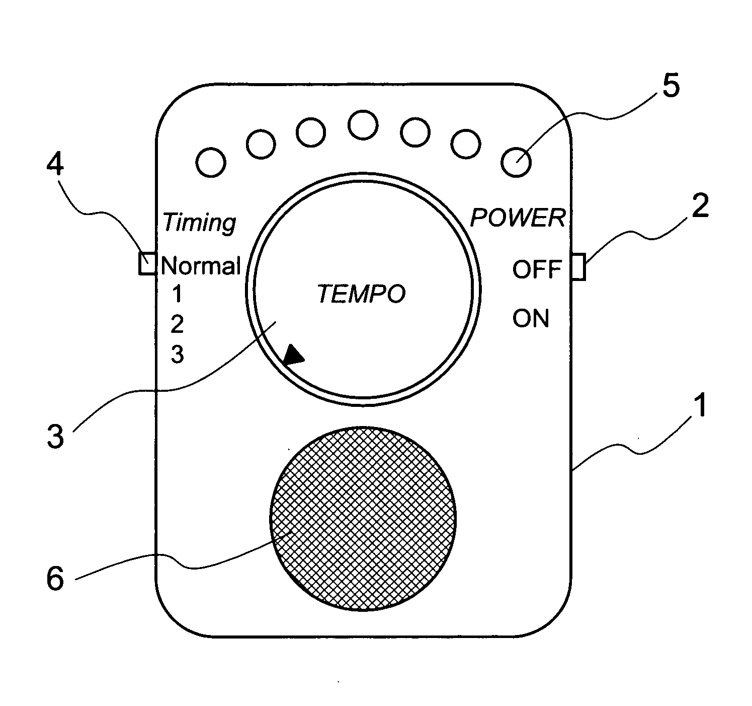
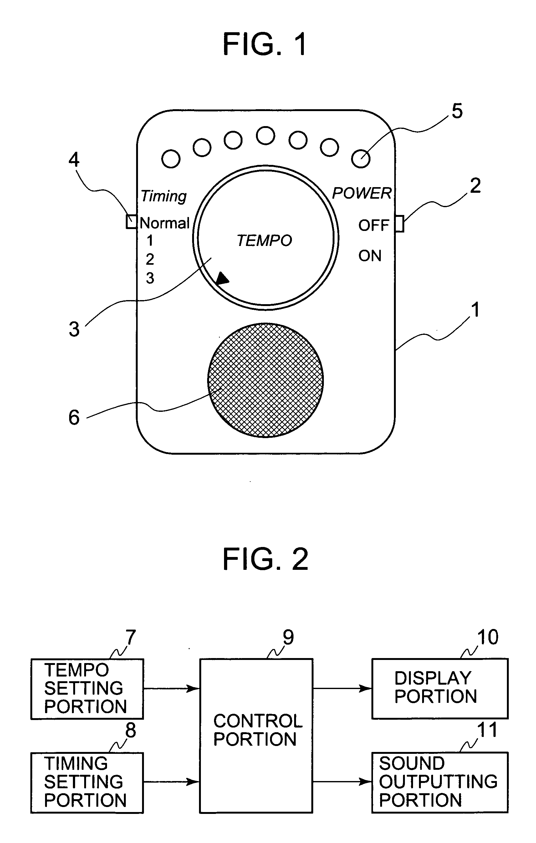
[0016]FIG. 1 is a front view of an electronic metronome according to an example of the embodiment of the present invention. A power source switch 2, a tempo switch 3, a timing switch 4, a tempo displaying portion 5, and a speaker 6 are disposed in a body case 1. If the power source switch 2 is operated to turn the metronome on and a desired tempo is set using the tempo switch 3, the tempo displaying portion 5 displays a tempo as a reciprocating movement by, for example, being lit up on the basis of a set value. The speaker 6 emits a sound in accordance with the tempo. In this manner, the metronome performs its function. The timing switch 4 sets a sound emission timing for the reciprocating movement of the tempo displaying portion 5. The speaker 6 usually emits a sound based on a tempo set at both ends of the reciprocating movement of the metronome. However, by operating the ti...


PUM


Abstract

To provide an electronic metronome making a display similar to the movement of a mechanical metronome or a parabolic movement, an electronic metronome of the present invention includes a timing setting portion for setting a timing for emitting a sound, a control portion that outputs pieces of tempo indication data and a tempo sound signal, which are based on a piece of data on a set tempo, respectively at timings based on a piece of sound emission timing information set by the timing setting portion, a display portion that is constructed of a plurality of light emitting elements or liquid crystal display segments and visually displays a tempo by sequentially displaying the pieces of tempo indication data outputted from the control portion, and a sound emitting portion that emits a sound through amplification of the tempo sound signal outputted from the control portion.

Description

BACKGROUND OF THE INVENTION [0001] 1. Field of the Invention [0002] The present invention relates to a method of indicating a tempo of an electronic metronome that is used in, for example, practicing playing an instrument. [0003] 2. Description of the Related Art [0004] Conventionally, with a view to expressing a pendular movement of a pointer of a mechanical metronome, there has been widely employed a method of expressing the pendular movement by arranging a plurality of light emitting elements such as light emitting diodes or liquid crystal segments along a line and lighting them up sequentially from one end to the other (e.g., as disclosed in JP 2000-88977 A (pages 1 to 17, FIG. 2)). Further, there has also been devised and put into practice a technique of reproducing a movement similar to the pendular movement with a small number of light emitting elements by changing the illuminances of the light emitting elements in accordance with a tempo (e.g., as disclosed in JP 09-133779 A...

Claims


Application Information

Patent Timeline
IPC IPC(8): G09B15/00G10H1/40G04F5/02G10H7/00
CPCG09B15/00G04F5/025
Inventor KOBAYASHI, AKIKO
Owner SEIKO INSTR INC
Why Eureka
Try Eureka