Cap frame and cap-frame setting frame

a technology of cap frame and setting frame, which is applied in the direction of embroidering machine, automatic machine, textiles and paper, etc., can solve the problems of not being able to easily align the center of the cap frame, so as to achieve easy and surely alignment

Active Publication Date: 2005-09-29
BROTHER KOGYO KK
View PDF7 Cites 4 Cited by
  • Summary
  • Abstract
  • Description
  • Claims
  • Application Information

AI Technical Summary

Benefits of technology

[0010] Therefore, an object of this invention is to provide a cap frame and a cap-frame ...

Problems solved by technology

As a result, the center of the cap frame could not necessarily be easily aligned with the center of the cap.
However, since the position of the center line is greatly remote from the area to be embroidered, it is not so easy to align the center of the cap frame with the center of the cap by visually checking the center line.
However, this holdi...

Method used


Image

  • Cap frame and cap-frame setting frame
  • Cap frame and cap-frame setting frame
  • Cap frame and cap-frame setting frame

Examples


first embodiment

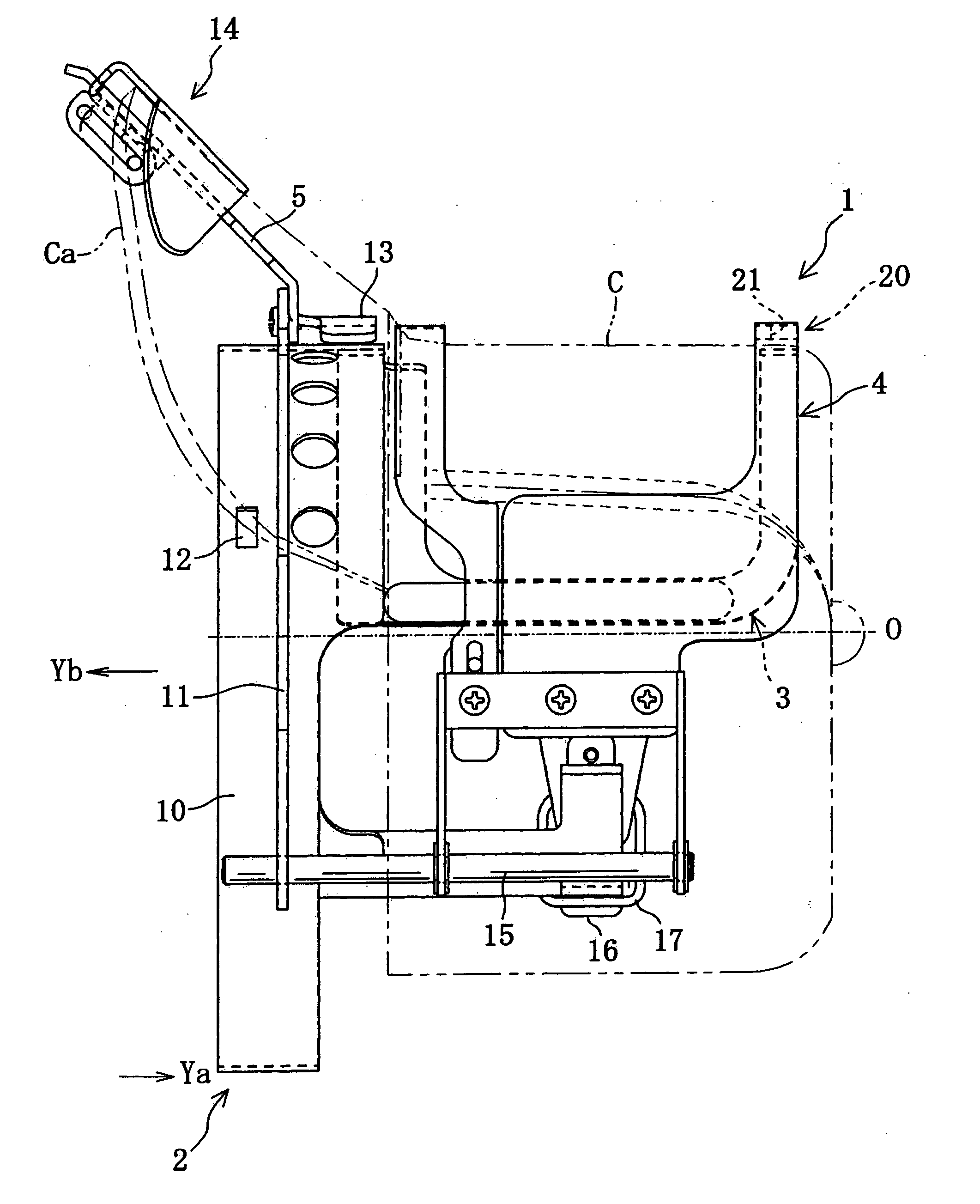
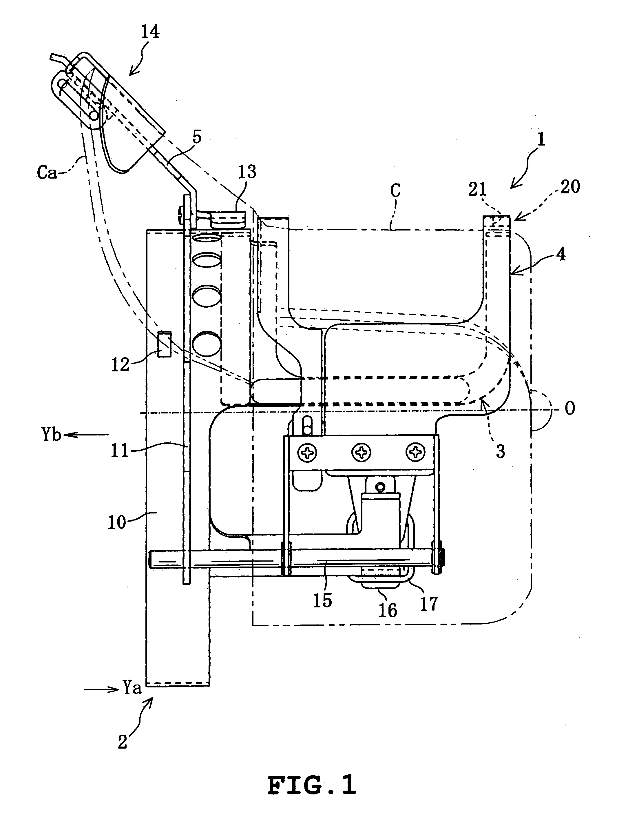
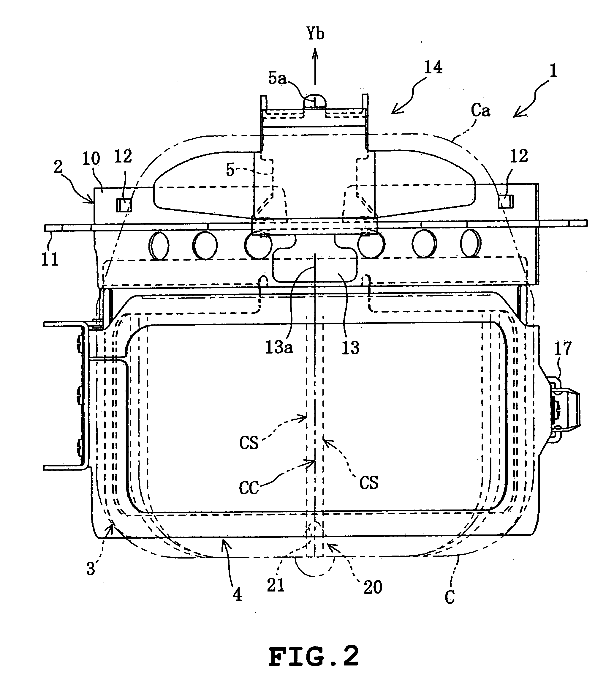
[0041] Now referring to FIGS. 1 to 8, an explanation will be given of this invention. In this embodiment, this invention is applied to an industrial multi-head embroidery sewing machine capable of simultaneously doing embroidery for plural caps. In this embodiment, it is assumed that the embroidery is done on the front of a baseball cap C. Incidentally, in following explanation, as seen from FIG. 8, it is assumed that the direction in which an operator sits for the multi-head sewing machine is a front direction; the front-rear direction is a Y direction and the left-right direction is an X direction. In FIG. 1, the direction of arrow Ya is the front direction, and in FIGS. 1, 2 and others, the direction of Yb is the rear direction from which a cap frame is mounted (or fit).

[0042] First, referring to FIG. 8, an explanation will be given of the configuration of a body of a multi-head sewing machine M. The body of the multi-head sewing machine M includes an embroidery-machine base fram...

third embodiment

[0078] Next referring to FIGS. 11 to 14, an explanation will be given of this invention. In this embodiment, this invention is applied to a cap-frame setting frame 30 with a cap frame 60 for holding the cap C being detachably attached. In this embodiment, the cap frame 60 is a cap frame of “non-frame” type. Incidentally, in the following description, it is assumed that the direction indicated by arrow Ya in FIG. 11 is a forward direction, and others.

[0079] As seen from FIGS. 11 to 14, the cap-frame setting frame 30 according to the invention includes a base frame 31 to which a cap frame body 61 of the cap frame 60 is attached in its positioned status, a fixing mechanism 40 provided at the rear end of the base frame 31 for fixing the cap-frame setting frame 30 to the working table 9, etc.

[0080] The fixing mechanism 40 includes an attaching member 40 having a ⊃-shape when viewed from the side, a screw member 42 screw-engaged to pass through a screw hole of the lower part of the attac...


PUM


Abstract

A cap frame includes a cap frame body to be detachably coupled with a coupling unit (and cap-frame setting frame) of an embroidery sewing machine M1, a cap supporting segment integrally attached to the cap frame body having a curved frame shape, in which the cap is set in a state put on from the outside, a holding-down member for holding down the vicinity of the area to be embroidered of the cap C from outside onto the cap supporting segment, and a cap central reference area of a V-shape recess formed at a circumferential center of an edge on a cap top side of the cap supporting segment, which is tactually recognizable from the outside of the cap C put on the cap supporting segment. In setting the cap, an operator can easily align the center of the cap with the cap central reference area while recognizing the cap central reference area in touch therewith through the cloth of the cap by his/her hand/finger.

Description

BACKGROUND OF THE INVENTION [0001] 1. Field of the Invention [0002] This invention relates to a cap frame for holding a cap in order to do embroidery by an embroidery sewing machine and a cap-frame setting frame used when the cap is attached to or detached from the cap frame. [0003] 2. Description of the Related Art [0004] Conventionally, there has been proposed an embroidery sewing machine capable of doing embroidery on a front or left / right side of a cap such as a baseball cap. In such an embroidery sewing machine, with a cap having been previously set in a cap frame, by detachably coupling the cap frame with a moving mechanism of the embroidery sewing machine, the embroidery can be done on the cap. Further, generally, when an operator makes an operation of attaching / detaching the cap for the cap frame, a cap-frame setting frame fixed to an operating stand is used. In this case, after the cap frame has been attached to the cap-frame setting frame, the cap is kept on or taken from ...

Claims


Application Information

Patent Timeline
IPC IPC(8): D05B39/00D05C9/04
CPCD10B2501/042D05C9/04
Inventor KAWAGUCHI, YASUHIKONOGUCHI, YASUKAZU
Owner BROTHER KOGYO KK
Why Eureka
Try Eureka