Tire manufacturing method, and green tire manufacturing equipment
a technology for green tires and manufacturing methods, which is applied in the field of tire manufacturing methods and green tire manufacturing equipment, can solve the problems of not being able to tune-up a tire by turning up the bead portions of the tire, and not having the kind of turn-up structure of the tire, etc., and achieves the effect of superior effect and easy production
- Summary
- Abstract
- Description
- Claims
- Application Information
AI Technical Summary
Benefits of technology
Problems solved by technology
Method used
Image
Examples
first embodiment
[0059] With reference to the drawings, a detailed description of a first embodiment of the present invention will be made, hereinafter.
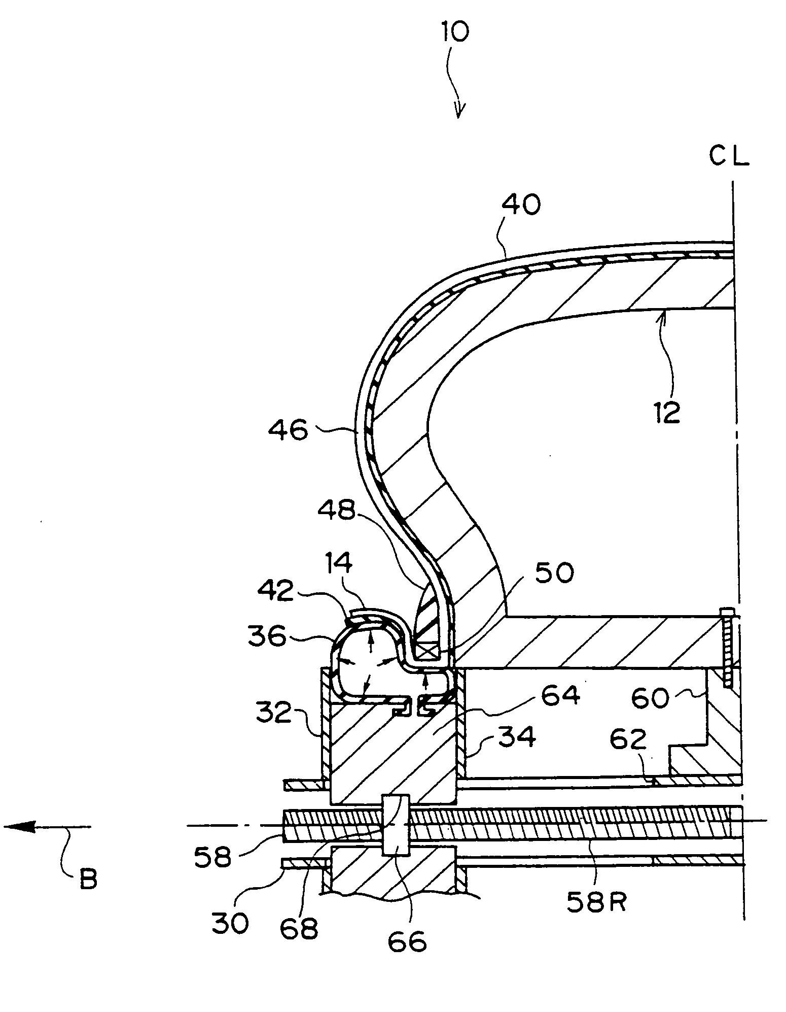
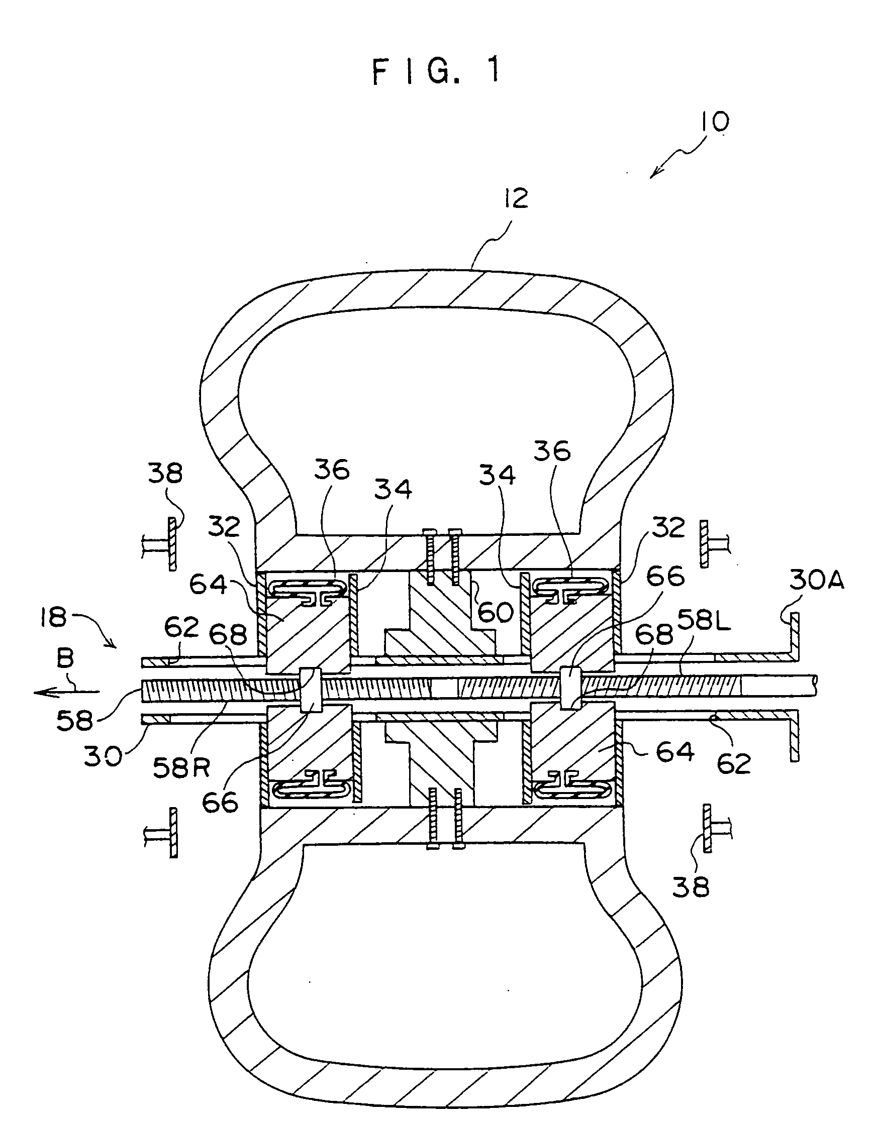
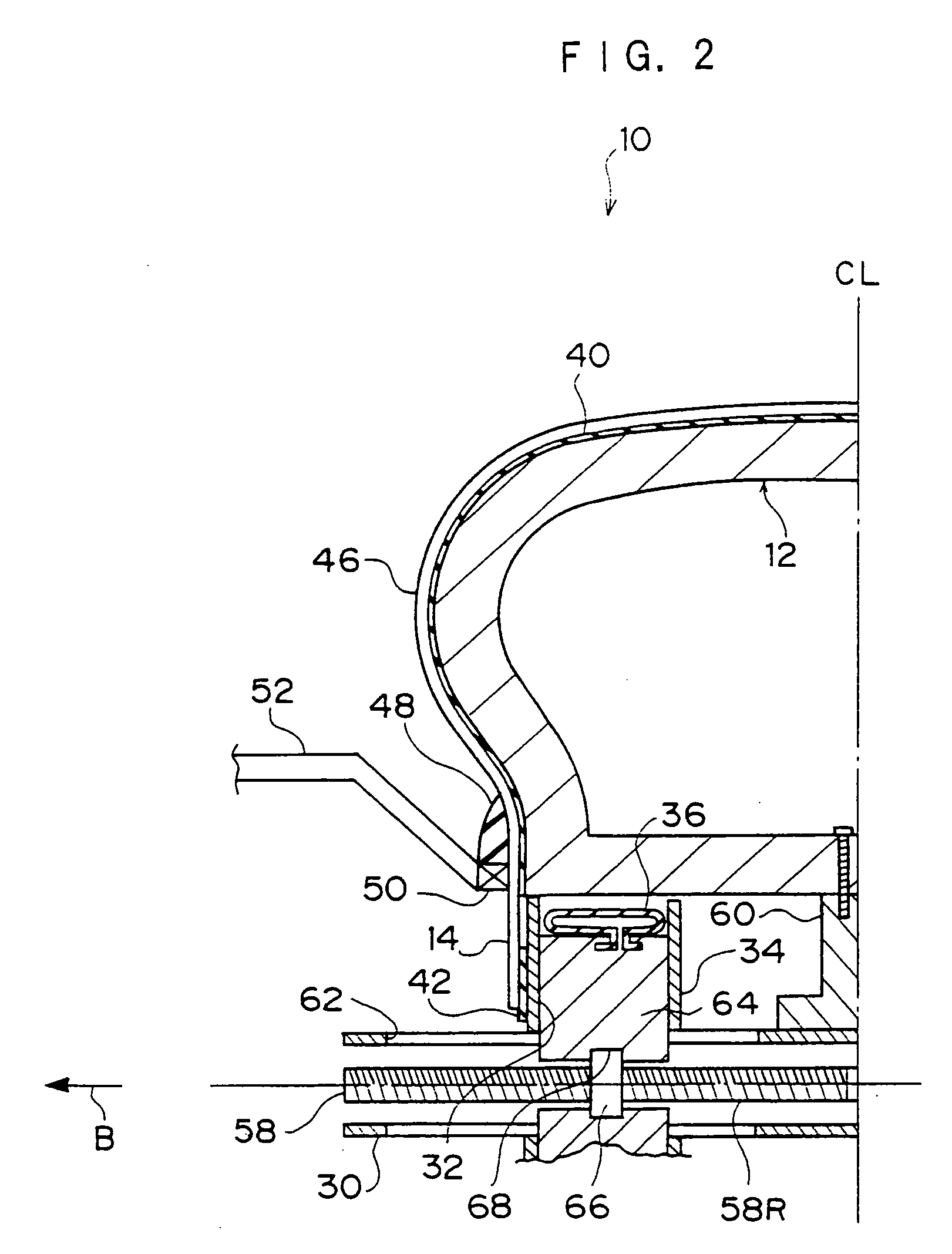
[0060] As shown in FIGS. 1 to 3, an apparatus 10 for manufacturing a green tire comprises a toroidal hard core 12, a setting mechanism 16 for setting a rubber-coated steel cord 14, a turn-up mechanism 18 for turning up a carcass, a pressing mechanism 20, and a bead holding arm 52.
[0061] The setting mechanism 16 comprises an unillustrated feeding portion for stocking therein the rubber-coated steel cord 14 and a setting portion 22 for setting the steel cord 14.
[0062] The setting portion 22 comprises an arm 24 through an inner portion of which the steel cord 14 is passed, and a swing portion 28 which is structured to be able to rotate around a rotational axis 26 disposed at a tip end of the arm 24 and feed the steel cord 14.
[0063] The turn-up mechanism 18 comprises a cylindrical main shaft external cylinder 30 disposed at the shaft of the hard core...
second embodiment
[0097] Next, a second embodiment of a tire manufacturing method of the present invention will be described. Further, structures identical to those in the first embodiment are denoted by the same reference numerals and descriptions thereof are omitted.
[0098] As shown in FIG. 8, in the present embodiment, in place of the engaging plate 32, a carcass engaging portion 36A is formed integrally with a side surface of the bladder 36, and the rubber sheet 42 is set onto the carcass engaging portion 36A to turn up the steel cord 14.
[0099] When the bladder 36 is inflated, the steel cord 14 is turned up with a portion of the carcass engaging portion 36A, as shown in FIG. 9.
[0100] Thereafter, a green tire is formed in the same manner as in the first embodiment of the present invention.
[0101] Further, a modified example of the bladder 36 is shown in FIG. 10A. For the bladder 36 shown in FIG. 10A, a carcass pressing portion 36B is formed integrally therewith, which, during inflation (shown by...
third embodiment
[0102] Next, a third embodiment of a tire manufacturing method of the present invention will be explained. Further, structures identical to those in the first embodiment are denoted by the same reference numerals, and descriptions thereof are omitted.
[0103] The present embodiment is a tire manufacturing method in which the steel cord 14 is turned up without using the bladders 36.
[0104] As shown in FIG. 11, the turn-up mechanism 18 of the present embodiment comprises an L-shaped arm 54 that can be inserted into the hard core 12.
[0105] Further, although only a single arm 54 is shown in FIG. 11, in fact, a plurality of arms 54 is provided along a circumferential direction of the hard core 12 at a predetermined interval.
[0106] A roller 56 is supported at a tip end of each arm 54 so as to be able to rotate freely.
[0107] In the present embodiment, firstly, as shown in FIG. 11, the roller 56 is disposed in the vicinities of inner edge portions of the hard core 12, and the rubber sheet...
PUM
 Abstract
Description
Claims
Application Information
 - R&D
- Intellectual Property
- Life Sciences
- Materials
- Tech Scout
- Unparalleled Data Quality
- Higher Quality Content
- 60% Fewer Hallucinations
Browse by: Latest US Patents, China's latest patents, Technical Efficacy Thesaurus, Application Domain, Technology Topic, Popular Technical Reports.
© 2025 PatSnap. All rights reserved.Legal|Privacy policy|Modern Slavery Act Transparency Statement|Sitemap|About US| Contact US: help@patsnap.com


