Dual sensor freepoint tool

a freepoint and tool technology, applied in the field of downhole tools, can solve the problems of affecting the operation of drilling operations, the connection of drill string and otherwise stuck, and the need to stop all drilling operations

Inactive Publication Date: 2005-09-29
WEATHERFORD TECH HLDG LLC
View PDF34 Cites 31 Cited by
  • Summary
  • Abstract
  • Description
  • Claims
  • Application Information

AI Technical Summary

Benefits of technology

[0017] In one aspect of the invention, the apparatus contains spring-loaded anchoring mechanisms that provide reliable means of solidly attaching the freepoint tool to a stuck tubular and allow easy retrieval of the fr

Problems solved by technology

Because of the non-linear path through the wellbore, the drill string can become bound or other wise stuck in the wellbore as it moves axially or rotationally.
The issues related to a stuck drill string are obvious.
All drilling operations must be stopped and valuable rig time lost.
Because the drill string is so long, determining the exact location of the obstruction can be difficult.
Several factors have a negative impact on the accuracy of this method.
A common problem associated with freepoint tools is the need to provide both a means of positively anchoring the ends of the freepoint tool when a measurement is being taken and also being able to freely move the tool to a new location within the tubular.
A problem associated with this system is that the bow springs are in constant contact with the inside surface of the stuck tubular as the freepoint tool is being lowered into the stuck tubular on a run in string.
This technique can lead to overheating of the motor and eventual failure of the motor windings.
Another problem associated with this type of arrangement occurs when attempting to anchor the freepoint tool in a horizontal section of a stuck tubular.
The weight of the freepoint tool may s

Method used


Image

  • Dual sensor freepoint tool
  • Dual sensor freepoint tool
  • Dual sensor freepoint tool

Examples


Embodiment Construction

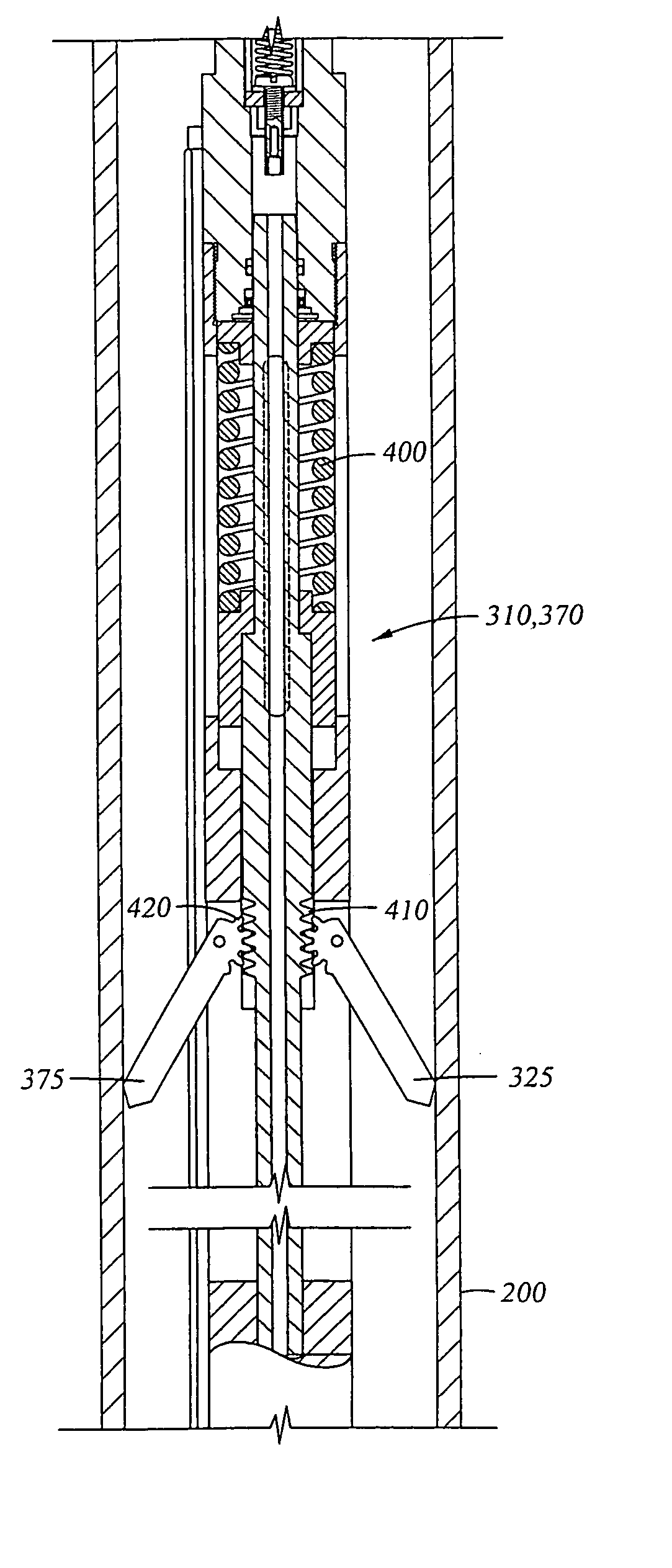
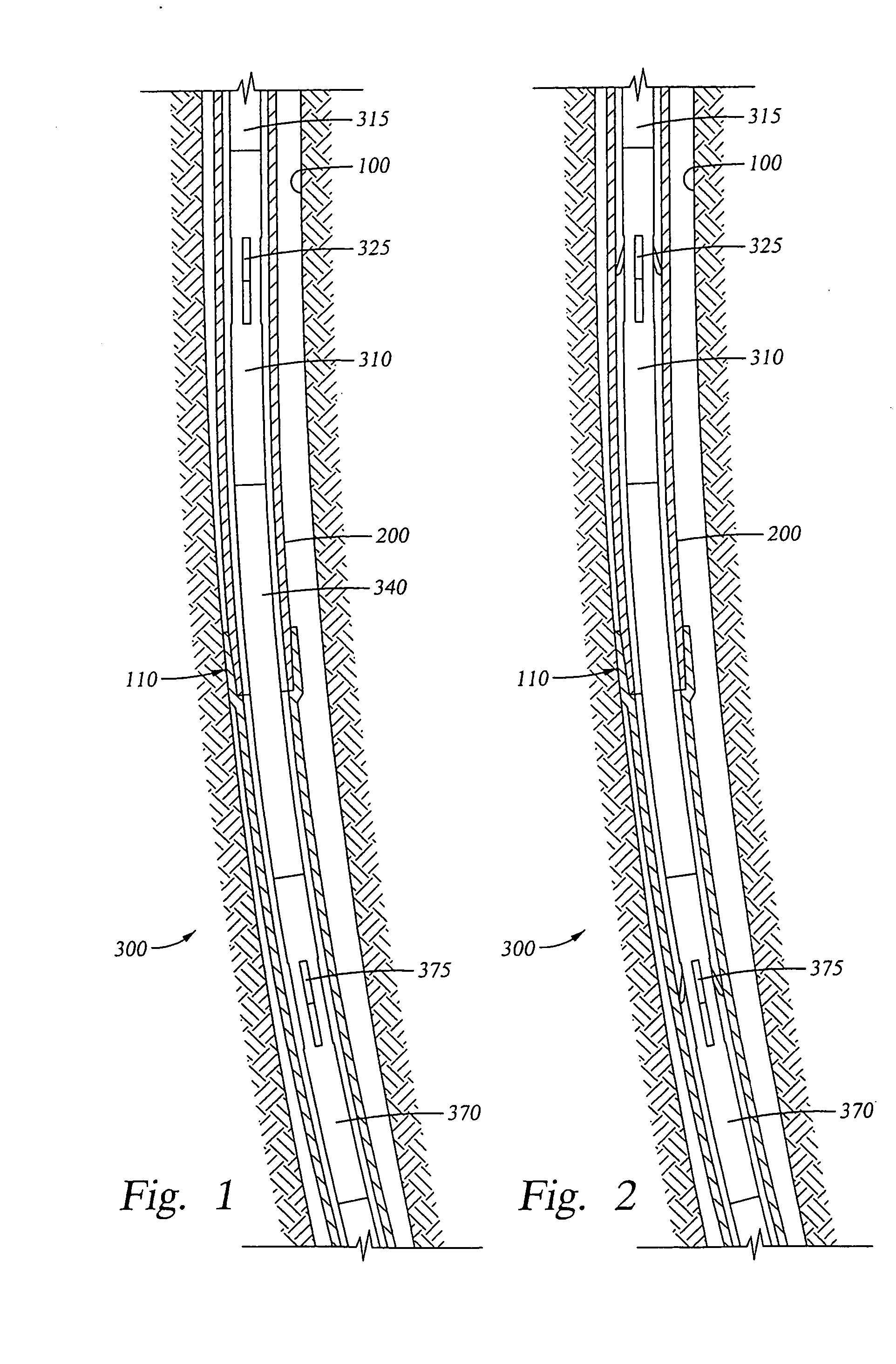
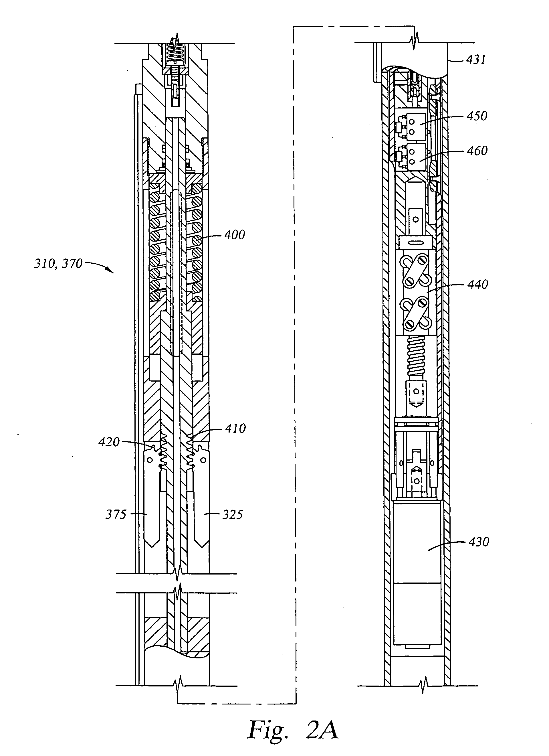
[0037]FIG. 1 is a partial section view of a freepoint tool 300 attached to the end of a run in string 315. Both the run in string 315 and the freepoint tool 300 are located within a drill string 200 stuck in a wellbore 100 at sticking point 110. The freepoint tool 300 is comprised of an upper anchor assembly 310, a dual sensor assembly 340 and a lower anchor assembly 370. The upper anchor assembly 310 and the lower anchor assembly 360 provide a means of attaching each end of the freepoint tool 300 to the stuck drill string 200, while the dual sensor assembly 340 is capable of measuring the response of the drill string 200 to either a tensile or torsional force applied at the surface.

[0038]FIG. 2 is a partial section view of a run in string 315 with a freepoint tool 300 anchored within a drill string 200 that is stuck in a wellbore 100 at sticking point 110. In this Figure, the upper anchor arms 325 and the lower anchor arms 375 are shown engaged with the inner surface of the drill ...


PUM


Abstract

An apparatus and method of determining the point at which a tubular is stuck within another tubular or a wellbore by applying a tensile or torsional force to the stuck tubular and measuring the response of various locations within the tubular. In addition, the apparatus may be combined with a cutting tool to separate the free portion of the tubular from the stuck portion.

Description

CROSS-REFERENCE TO RELATED APPLICATIONS [0001] This application is a continuation-in-part of U.S. patent application Ser. No. 10 / 211,252, filed Aug. 2, 2002, which claims benefit of U.S. provisional patent application Ser. No. 60 / 310,124, filed Aug. 3, 2001. Both applications are herein incorporated by reference. [0002] This application is a continuation-in-part of U.S. patent application Ser. No. 10 / 967,588 (Atty. Docket No. WEAT / 0596), filed Oct. 18, 2004, which is herein incorporated by reference. [0003] U.S. Pat. No. 6,712,143 (Atty. Docket No. WEAT / 0265.C1) and U.S. Pat. No. 6,722,435 (Atty. Docket No. WEAT / 0266.X1) are herein incorporated by reference.BACKGROUND OF THE INVENTION [0004] 1. Field of the Invention [0005] The present invention relates to an apparatus and method for use in a wellbore. More particularly, the invention relates to a downhole tool for determining the location of an obstruction in a wellbore. More particularly still, the invention relates to a downhole ...

Claims


Application Information

Patent Timeline
IPC IPC(8): E21B29/00E21B31/00E21B47/09
CPCE21B29/005E21B47/09E21B31/002
Inventor GRAY, KEVIN L.ESTES, JAMES D.
Owner WEATHERFORD TECH HLDG LLC
Why Eureka
Try Eureka