Fuel tank disposition structure of vehicle

a technology of fuel tank and disposition structure, which is applied in the direction of vessel construction, marine propulsion, transportation items, etc., can solve the problems of increased weight of the vehicle, difficulty in facilitating a walk-through arrangement in the vehicle width direction, and inability to achieve proper utilization of space during seat arrangement, etc., to achieve sufficient tank volume and improve the function of vehicle side crash

Active Publication Date: 2005-09-29
MAZDA MOTOR CORP
View PDF4 Cites 45 Cited by
  • Summary
  • Abstract
  • Description
  • Claims
  • Application Information

AI Technical Summary

Benefits of technology

[0007] The present invention has been devised in view of the above-described problems. An object of the present invention is to provide a fuel tank disposition structure of a vehicle which can ensure the sufficient tank volume, the roomy cabin in the vertical direction and the proper foot space of passenger, and improve the function for the vehicle side crash and attain the seat arrangement properly.

Problems solved by technology

However, this structure has a problem that since the fuel tank is disposed so as to extend in the vehicle width direction, some measures against a vehicle side crash may be necessary and protecting the fuel tank with frames enclosing the fuel tank may cause a weight increase of the vehicle.
Thus, this conventional structure has another problem that a proper utilization of space during a seat arrangement of the vehicle may not be attained.
Accordingly, this conventional structure may need a relatively large-sized tunnel portion, and it may be difficult to facilitate a walk-through arrangement in the vehicle width direction.
Thus, this conventional structure may not be suitable for the compact car particularly, either.

Method used


Image

  • Fuel tank disposition structure of vehicle
  • Fuel tank disposition structure of vehicle
  • Fuel tank disposition structure of vehicle

Examples


Embodiment Construction

[0097] Hereinafter, preferred embodiments of the present invention will be described in detail referring to the accompanying drawings. It should be understood that even though embodiments are separately described, single features thereof may be combined to additional embodiment.

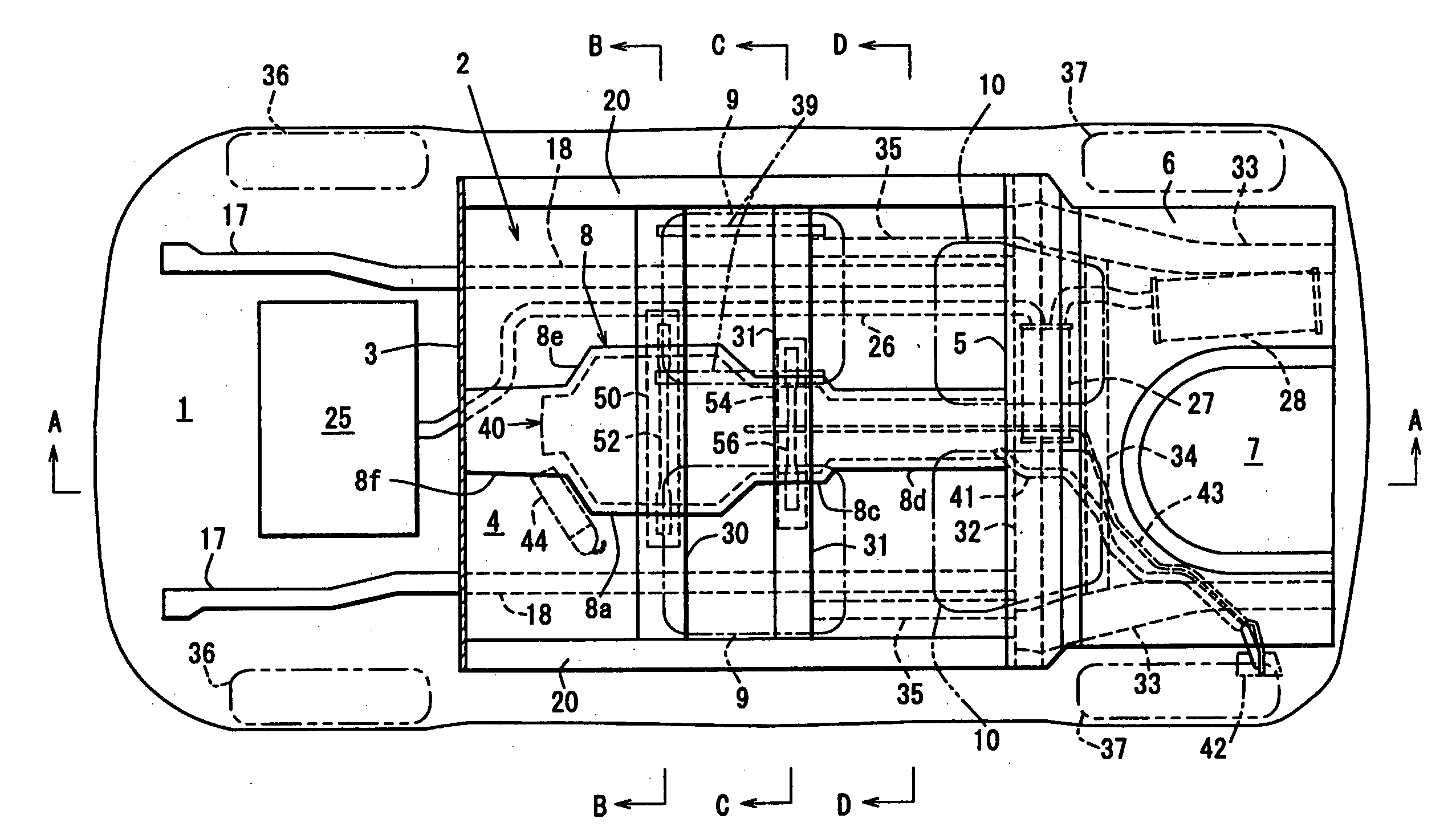
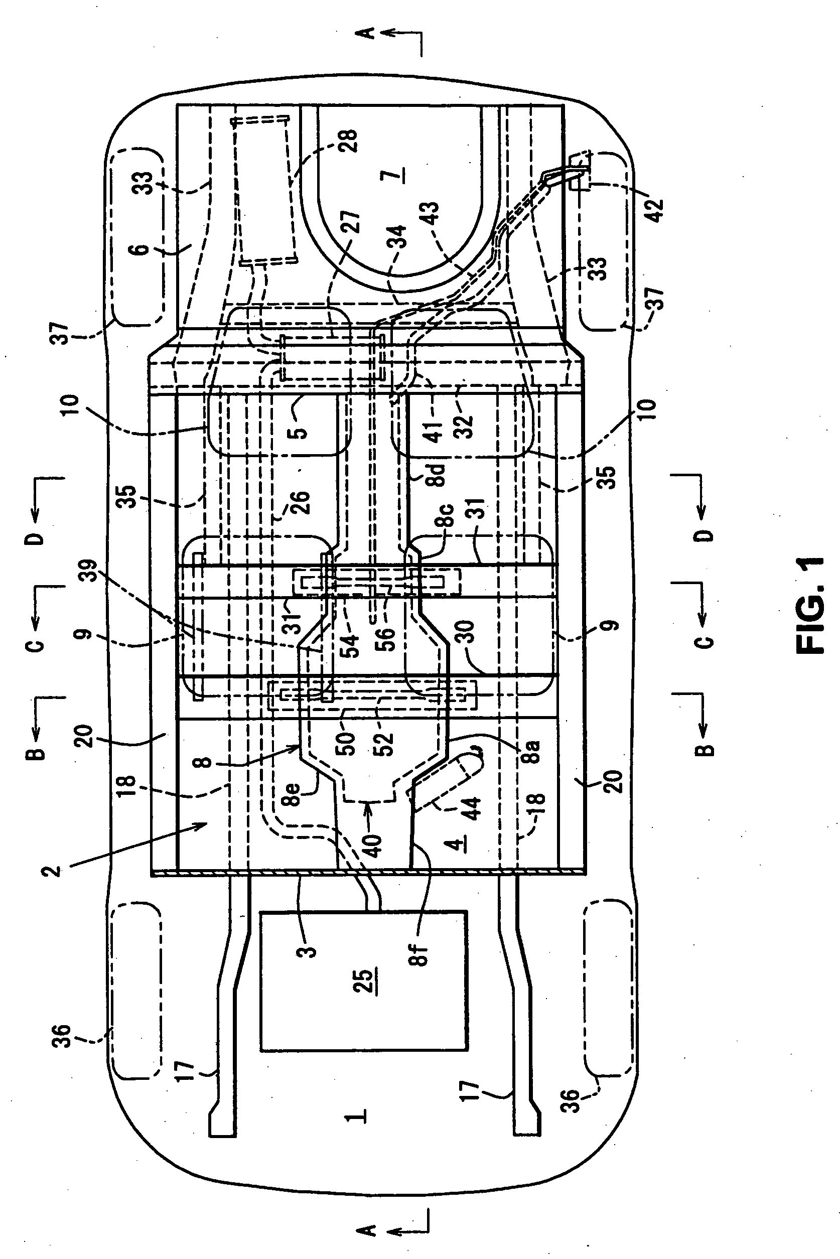
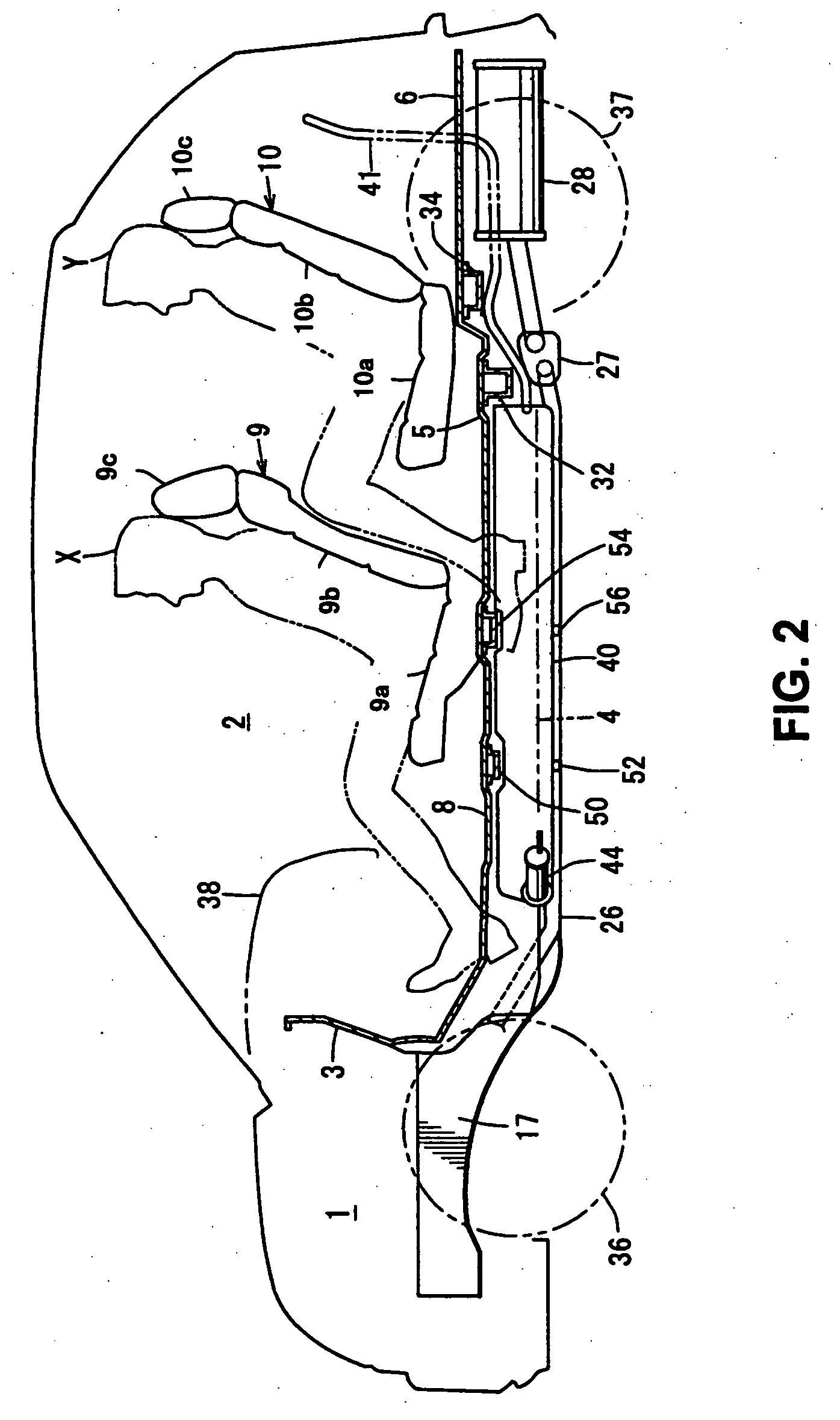
[0098] Figures illustrate a fuel tank disposition structure of a vehicle, and as illustrated in FIGS. 1, 2 and 3, there is provided a dash lower panel (dash panel) 3 which separates a cabin 2 from an engine room 1 in a longitudinal direction of a vehicle. A floor panel 4 which forms a lower face of the cabin 2 is connected with a lower end portion of the dash lower panel 3. The floor panel 4 extends substantially horizontally from the front to the rear of the vehicle. A rear floor panel 6 is integrally connected with a rear end portion of the floor panel 4 via a kickup portion 5, and a spare tire pan 7 is formed at a central portion of the rear floor panel 6 so as to be located in a lower position. There is ...


PUM


Abstract

There is provided the fuel tank disposition structure of the vehicle, in which a plurality of passenger seats are disposed longitudinally in the cabin, comprising the tunnel portion provided so as to project upward toward the inside of the cabin at the central portion of the floor panel forming the lower face of the cabin, the tunnel portion including the wide portion and the narrow portions, the fuel tank disposed in the tunnel portion below the floor panel, the fuel tank including the wide portion and the narrow portion so as to correspond to the tunnel portion, wherein the front seat is disposed above the wide portion of the tunnel portion, and the rear seat is disposed above the narrow portions.

Description

BACKGROUND OF THE INVENTION [0001] The present invention relates to a fuel tank disposition structure of a vehicle in which a plurality of passenger seats are disposed longitudinally in a cabin. [0002] Conventionally, the following structure is known as such a fuel tank disposition structure of a vehicle. Namely, there is provided a tunnel portion which projects upward toward an inside of the cabin at a central portion of a floor panel forming a lower face of the cabin in a vehicle width direction. And, there are further provided a central projecting portion which further projects upward from the above-described tunnel portion between a driver seat and a assistant seat, and a pair of side projecting portions which respectively project upward from portions of the floor panel below respective seat cushions of the driver and assistant seats. Herein, the side projecting portions are formed so as to extend in the vehicle width direction between the tunnel portion and side sills, and a fu...

Claims


Application Information

Patent Timeline
Patent Type & Authority Applications(United States)
IPC IPC(8): B60K15/063B60K15/067B62D21/02B62D21/10
CPCB62D21/10B60K15/063
Inventor ITO, AKIRASUMIDA, KAZUEOKANA, FUMIOKUSU, HIROTAKAMORIYAMA, NAOMUNE
Owner MAZDA MOTOR CORP
Why Eureka
Try Eureka