
Sheet processing apparatus and image forming apparatus having same

a technology of image forming apparatus and processing apparatus, which is applied in the direction of electrographic process, instruments, transportation and packaging, etc., can solve the problems of affecting productivity and increasing the tendency of such skews, and achieve the effect of improving the accuracy of punching positions and not reducing productivity

Inactive Publication Date: 2005-09-29
CANON KK
View PDF13 Cites 38 Cited by
  • Summary
  • Abstract
  • Description
  • Claims
  • Application Information

AI Technical Summary

Benefits of technology

[0015] The invention is made in view of the problems described above. Accordingly, it is an object of the invention to provide a sheet processing apparatus that improves punched position accuracy without diminishing productivity even when skew correction is performed at the time of punch processing.

Problems solved by technology

However, problems occur with the sheet processing apparatus wherein the sheet conveyance speed and the punch processing speed are synchronized to each other, and the punch processing is performed on a plurality of portions along a line parallel or perpendicular to the sheet conveyance direction without stopping the sheet being conveyed.
The problems are that when a sheet is fed into the punch unit in the state of the paper being skewed (state of the paper being skewed with respect to the conveyance direction), the punch processing is performed on the sheet in the state of the paper being kept skewed, whereby a plurality of punch holes are punched in the sheet along a skewed line on the sheet.
The tendency of such skew especially increases in a case where a conveyance path from the image forming apparatus to the punch unit is long.
Especially, compared to the case where the punch processing is not performed, productivity is significantly diminished in the case where the inter-sheet interval is short.

Method used


Image

  • Sheet processing apparatus and image forming apparatus having same
  • Sheet processing apparatus and image forming apparatus having same
  • Sheet processing apparatus and image forming apparatus having same

Examples


first embodiment

[0028] As a best mode for carrying out the invention, a first embodiment will be described in detail herebelow by using FIGS. 1 to 8.

[0029] (Description of Image Forming Apparatus)

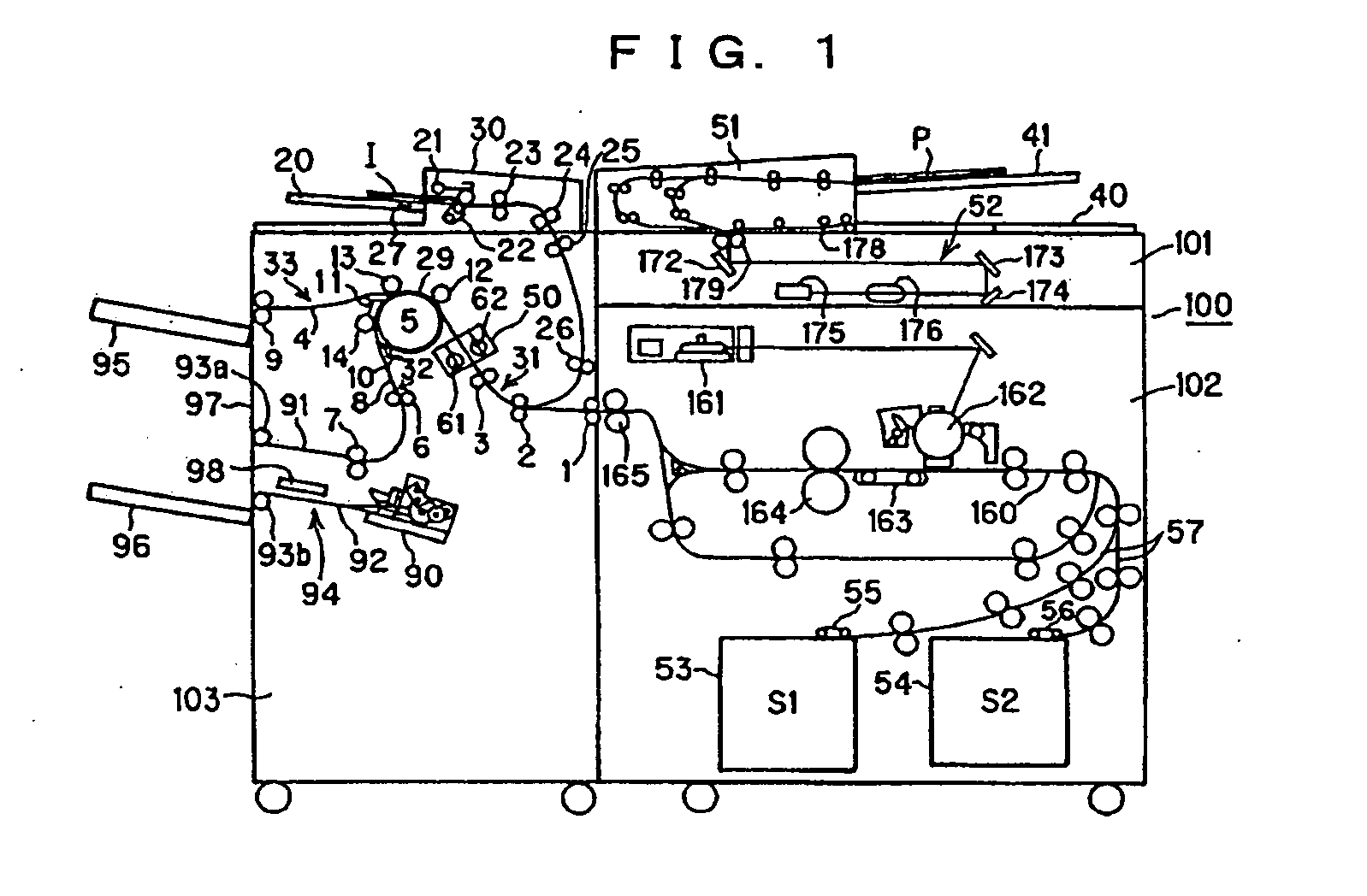
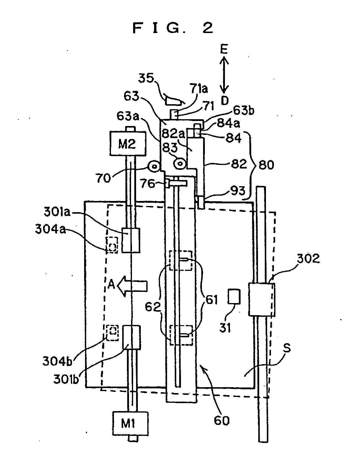
[0030] First, an image forming apparatus will be described. FIG. 1 is a longitudinal, sectional front elevation view showing the entirety of an image forming apparatus 100 constructed of a read-sheet feeding portion 101, an image forming apparatus mainbody 102, and a sheet processing apparatus 103 (also called “finisher”). FIG. 2 is a plan view of a punching device 50 provided in the sheet processing apparatus 103.

[0031] The read-sheet feeding portion 101 is constructed of an automatic original feeding portion 51 and an optical system 52. The optical system 52 feeds an original P set on an original tray 41 to a document read position and then conveys to a discharge position. The optical system 52 is constructed of a lamp 179 for illuminating the original P conveyed to the read position and placed over a...

second embodiment

[0118] In the first embodiment, the skew correction is performed in the state where the trail edge of the sheet is nipped by a conveyance roller pair 302. In this case, when the skew amount is large, deflection of the sheet between the registration roller pair 301 and the conveyance roller pair 302 is enlarged. The arrangement may be as described herebelow as a method for reducing the deflection.

[0119] Referring to FIG. 9, the conveyance roller pair 302 on the upstream side of the registration roller pair 301 in the sheet conveyance direction is configured to be movable in the direction intersecting with the sheet conveyance direction. In this configuration, during the skew correction by using the registration roller pair 301, the conveyance roller pair 302 is moved by a predetermined amount along the direction intersecting with the sheet conveyance direction in correspondence to the amount of skew correction. Thereby, the deflection of the sheet between the registration roller pai...

third embodiment

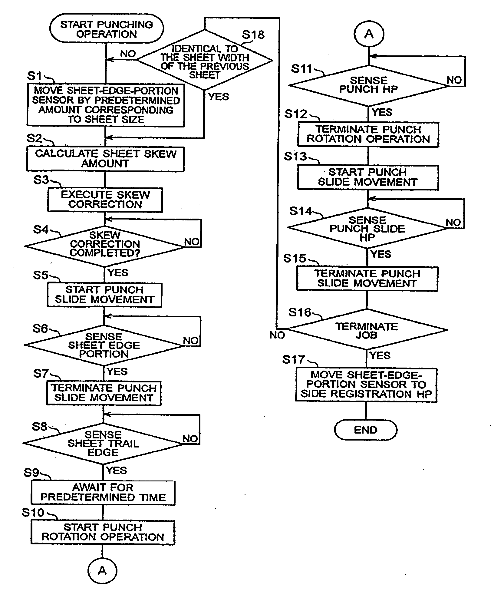
[0134] As the skew is larger, it takes a longer time for the skew correction. As such, when the skew of the sheet is large in a construction of the type shown in FIG. 2, a case can be contemplated wherein the trail edge of the sheet reaches the sheet detecting sensor 31 during the skew correction. For this reason, in a construction according to a third embodiment, when the trail edge of the sheet has reached the sheet detecting sensor 31 before termination of the skew correction, the punch processing of that sheet is inhibited. A flowchart regarding this case will be described herebelow by using FIG. 10.

[0135] First, it is determined whether or not the sheet detecting sensor 31 has detected a trail edge of a sheet (S101) If the sheet detecting sensor 31 has detected the trail edge of the sheet, then it is determined whether or not skew correction has been completed (S102). If the skew correction has been completed, then the CPU 2002 awaits for a predetermined time so that the punch...


PUM

PropertyMeasurementUnit
Sizeaaaaaaaaaa
Speedaaaaaaaaaa

Abstract

The invention comprises registration roller pairs which detect a skew amount of a sheet being conveyed; registration roller pairs which perform skew correction of the sheet while the sheet is being conveyed; a punch unit which performs punching of the sheet; a punch-unit driving portion which drives the punch unit; a sheet-edge detecting sensor which performs detection of a sheet edge in a direction intersecting with a sheet conveyance direction; a punch-unit moving device which moves the punch unit in the direction intersecting with the sheet conveyance direction; a sheet detecting sensor which performs detection of a sheet position in the sheet conveyance direction; and a controller portion which performs control such that after skew of the sheet is corrected by the registration roller pairs in accordance with detection results of skew amount sensors, and punching is performed on the sheet by the punch-unit moving device and the punch driving portion in accordance with a detection result of the sheet detecting sensor.

Description

BACKGROUND OF THE INVENTION [0001] 1. Field of the Invention [0002] The present invention relates to a sheet processing apparatus for performing sorting, binding, stacking, and the like operations for sheets being discharged from an image forming apparatus or the like. More specifically, the invention relates to a sheet processing apparatus having a punch unit for punching a hole(s) into a sheet(s). [0003] 2. Description of the Related Art [0004] Conventionally known sheet processing apparatuses includes a type that provides a post-process including, for example, sorting, binding, stacking, and hole punching to post-image-forming sheets being discharged from an image forming apparatus. [0005] In addition, known punching method for punching a punch hole(s) into a sheet(s) in a sheet processing apparatus of the type described above include, for example, a method that stops a sheet being discharged at a constant interval from an image forming apparatus and performs punch processing of ...

Claims


Application Information

Patent Timeline
IPC IPC(8): B26D5/00G03G15/00B26D7/26B26F1/02B65H9/00B65H9/10B65H33/04B65H37/04B65H43/04
CPCB26D5/00B26D7/2628B26F1/02B65H9/002G03G2215/00818B65H2301/331B65H2301/44318G03G15/6538B65H9/103
Inventor MORIYAMA, TSUYOSHIHANADA, TAKAKOTAIRA, MASAYOSHINISHIKATA, AKINOBUTOMIYASU, HIROAKI
Owner CANON KK
Features
  • Generate Ideas
  • Intellectual Property
  • Life Sciences
  • Materials
  • Tech Scout
  • Unparalleled Data Quality
  • Higher Quality Content
  • 60% Fewer Hallucinations
Learn More